Pressure stabilizing nail structure for compensating flow force in closing direction of internal flow type cartridge valve

A technology of voltage stabilizing nails and cartridge valves, which is applied in the field of voltage stabilizing nail structures, and can solve problems such as interference and proportional control interference of cartridge valves

Inactive Publication Date: 2018-06-15
ZHEJIANG UNIV
View PDF9 Cites 2 Cited by
  • Summary
  • Abstract
  • Description
  • Claims
  • Application Information

AI Technical Summary

Problems solved by technology

However, in practical applications, the poppet valve spool is easily disturbed by hydraulic force when it is working, and because the cartridge valve itself is used for high pressure and large flow characteristics, the hydraulic force interferes more seriously with the spool. For the cartridge valve, the proportional control caused great disturbance

Method used


Image

  • Pressure stabilizing nail structure for compensating flow force in closing direction of internal flow type cartridge valve
  • Pressure stabilizing nail structure for compensating flow force in closing direction of internal flow type cartridge valve
  • Pressure stabilizing nail structure for compensating flow force in closing direction of internal flow type cartridge valve

Examples


Embodiment Construction

[0021] The present invention will be further described below in conjunction with accompanying drawing and example.

[0022] Embodiments of the present invention are as follows:

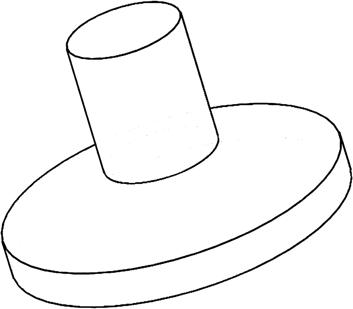
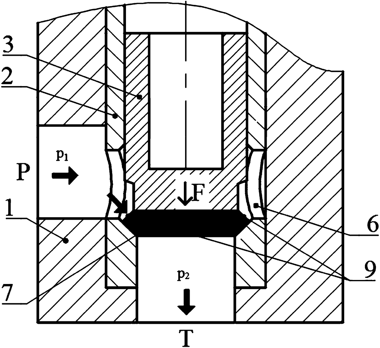
[0023] Using internal flow cartridge valves, such as figure 1 and figure 2 As shown, it includes valve body 1, valve sleeve 2, valve core 3, voltage stabilizing nail connecting rod 4 and the boss 5 at the end of the voltage stabilizing nail. The valve core 3 is set in the valve body 1 through the valve sleeve 2. Oil inlet P and oil return port T respectively. The oil inlet P is opened on the side wall of valve body 1, and the oil return port T is opened on the bottom end surface of valve body 1. The oil inlet P and oil return port T pass through The inner chamber of the valve body 1 communicates with the channel.

[0024] The valve sleeve 2 is set in the channel of the inner cavity of the valve body 1 , and the valve core 3 is set in the valve sleeve 2 . The valve sleeve 2 is installed inside the...


PUM


Abstract

The invention discloses a pressure stabilizing nail structure for compensating a flow force in the closing direction of an internal flow type cartridge valve. A plurality of throttle holes which are uniformly formed in a spaced manner circumferentially are formed in the periphery of the bottom of a valve sleeve of the cartridge valve; a chamfer is arranged at the inner edge of the inner end surface, close to an oil return port, of the valve sleeve; the chamber is matched with the outer edge of the bottom end surface of a valve element, close to the oil return port, and the pressure stabilizingnail structure is arranged on the bottom end surface of the valve element; the pressure stabilizing nail structure comprises a connecting rod of a pressure stabilizing nail and a tail boss of the pressure stabilizing nail, wherein one end of the connecting rod of the pressure stabilizing nail is fixed to the center of the bottom end surface of the valve element while the other end of the connecting rod of the pressure stabilizing nail is fixedly connected to the center of the small end surface of the tail boss of the pressure stabilizing nail, the large end surface of the tail boss of the pressure stabilizing nail faces downward and is parallel to the bottom end surface of the valve element, and the connecting rod of the pressure stabilizing nail, the tail boss of the pressure stabilizingnail and the valve element are arranged coaxially. The pressure stabilizing nail structure disclosed by the invention can compensate the flow force in the closing direction of the internal flow typecone valve, and can adjust the compensating degree of the flow force subjected to the valve element.

Description

technical field [0001] The invention relates to a pressure stabilizing nail structure for hydraulic power compensation of a valve core of a hydraulic valve, in particular to a pressure stabilizing nail structure for compensating the hydraulic power in the closing direction of an internal flow cartridge valve. Background technique [0002] Cartridge valves are widely used in various hydraulic control systems because of their simple structure, large flow rate, and fast action speed. Especially now, the combination of proportional technology and cartridge valves has further promoted the use of cartridge valves. Valve installation plays an important role in modern high-pressure and large-flow hydraulic systems. [0003] Because the flat-bottomed poppet valve not only inherits the good sealing and sensitivity of the ordinary full-cone poppet valve, but also has a larger flow capacity than the traditional full-cone poppet valve, so the main-stage spool of the cartridge valve mostl...

Claims


Application Information

Patent Timeline
IPC IPC(8): F16K1/32F16K1/36F16K47/02
CPCF16K1/32F16K1/36F16K47/023
Inventor 谢海波谭礼刘建彬杨华勇
Owner ZHEJIANG UNIV
Why Eureka
Try Eureka