Double-axis multi-force cylinder

A technology of multiple force and cylinder, applied in the direction of fluid pressure actuating device, etc., can solve the problems of increased machining accuracy requirements, easy deformation of the piston rod, unreasonable structural settings, etc., to achieve strong anti-bending and anti-torsion performance, not easy to deform or broken, easy to fine-tune effect

Active Publication Date: 2016-03-02
NINGBO INTELL PNEUMATIC TECH CO LTD
View PDF6 Cites 0 Cited by
  • Summary
  • Abstract
  • Description
  • Claims
  • Application Information

AI Technical Summary

Problems solved by technology

However, the output of the above-mentioned single-axis double-force cylinder depends on the number of air chamber units. When a larger output is required, more air chamber units need to be installed, resulting in the following defects: First, the increase in the number of air chamber units makes the cylinder The overall volume of the body increases accordingly, resulting in the need to occupy a large space during installation; secondly, the more the number of air chamber units, the longer the length of the piston rod is set, which makes the load on the piston rod heavier, resulting in the piston rod being in motion. It is easy to deform, break, etc., and the processing accuracy requirements are also increased, resulting in an increase in manufacturing costs
In order to avoid the large volume problem of single-axis multi-force cylinders, double-cylinder cylinders have also appeared on the market. However, in actual use, there are also situations where the piston rod is easily deformed and broken, and the existing double-cylinder cylinders Due to the unreasonable structural setting of the cylinder, there are still the following defects: due to the complicated structural setting, the assembly is difficult, the output effect is not good, and the actual use needs of users cannot be met; the stroke cannot be adjusted accurately, resulting in the control of the working state of the cylinder body. more inconvenient

Method used


Image

  • Double-axis multi-force cylinder

Examples


Embodiment Construction

[0013] The present invention will be further described below in conjunction with the accompanying drawings.

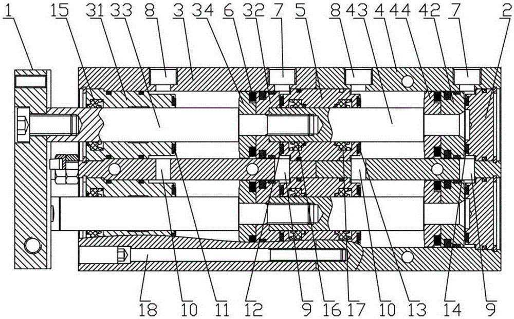
[0014] Such as figure 1 The shown biaxial multi-force cylinder includes a front end cover 1, a rear end cover 2, a first cylinder body 3, and a second cylinder body 4 that is mated and connected with the first cylinder body 3, and the second cylinder body 4 is installed Located on the rear end cover 2, the first cylinder body 3 and the second cylinder body 4 cooperate in the axial direction to form two side-by-side inner chambers, and the first air chamber unit and the second air chamber unit are respectively arranged in the two inner chambers. Two air chamber units, a connection seat 5 is provided between the first air chamber unit and the second air chamber unit, and the connection seat 5 is sealed and installed at the joint of the first cylinder body 3 and the second cylinder body 4 .

[0015] The first air chamber unit includes a guide seat 31 sealed in the first ...


PUM


Abstract

The invention discloses a double-shaft multi-tandem cylinder. The double-shaft multi-tandem cylinder comprises a front end cover, a rear end cover, a first cylinder body and a second cylinder body, wherein the first cylinder body and the second cylinder body are matched along the axial direction to form inner cavities which are arranged in parallel; a first air cavity unit and a second air cavity unit are respectively formed in the two inner cavities; the first air cavity unit comprises a guide set, a first piston and a first piston rod; the second air cylinder unit comprise a second piston and a second piston rod; the end part of the second piston rod is detachably connected with the first piston rod; a first magnetic seat which is matched with the first piston is arranged on the first piston rod; a second magnetic seat which is matched with the second piston is arranged on the second piston rod; air inlets and exhaust ports are respectively formed in the first cylinder body and the second cylinder body. The double-shaft multi-tandem cylinder has the advantages that the structure is simple and reasonable, the size is small, the output force is larger, the loads borne by the pistons are smaller, the manufacturing cost is lower, the assembly is convenient, the actual usage requirement of a user can be met, and the strokes and the working states of the piston rods are conveniently controlled.

Description

technical field [0001] The invention relates to the technical field of cylinders, in particular to a double-shaft multi-force cylinder. Background technique [0002] Double power cylinder is a kind of cylinder, which is composed of multi-layer pistons superimposed on each other. The output is multiplied and has the advantage of large output. It is suitable for oil-free operation occasions with short stroke and high output. The double-force cylinders currently on the market are usually single-axis double-force cylinders. on the pole. When working, the piston rod is driven synchronously by multiple pistons to achieve the effect of increasing output. However, the output of the above-mentioned single-axis double-force cylinder depends on the number of air chamber units. When a larger output is required, more air chamber units need to be installed, resulting in the following defects: First, the increase in the number of air chamber units makes the cylinder The overall volume o...

Claims


Application Information

Patent Timeline
Patent Type & Authority Patents(China)
IPC IPC(8): F15B15/17F15B15/24
Inventor 陈海斌竺伟杰朱建松毛夏平林开峰胡军
Owner NINGBO INTELL PNEUMATIC TECH CO LTD
Why Eureka
Try Eureka