
Electronic equipment and control method thereof

A technology of electronic equipment and control method, applied in the field of artificial intelligence, can solve the problems of wasting user time and energy, high power consumption of notebook computers, cumbersome operation, etc.

Inactive Publication Date: 2018-06-15
LENOVO (BEIJING) LTD
View PDF2 Cites 3 Cited by
  • Summary
  • Abstract
  • Description
  • Claims
  • Application Information

AI Technical Summary

Problems solved by technology

[0002] Current electronic devices, especially smart electronic devices, when users want to activate them, they need to turn them on first to enter the login mode, and then the device can be activated by using iris, fingerprint, face, or password input, which is cumbersome to operate
For example, most computers are turned on, and then the user enters the password before the user can use the computer normally, which wastes the user's time and energy
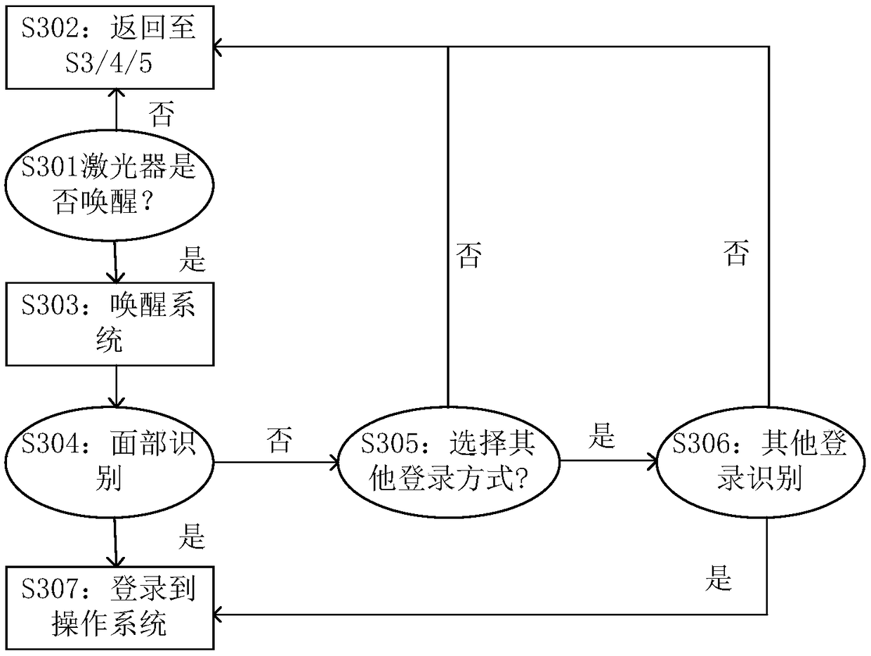
In addition, in order to reduce the user's login operation, many notebook computers usually use face recognition technology for login operation, which makes the camera need to be in a standby state all the time, thus causing the power consumption of the notebook computer to be too high even when it is turned off

Method used


Image

  • Electronic equipment and control method thereof
  • Electronic equipment and control method thereof
  • Electronic equipment and control method thereof

Examples


Embodiment Construction

[0019] The present invention will be described in detail below in conjunction with the accompanying drawings.

[0020] It should be understood that various modifications may be made to the embodiments disclosed herein. Accordingly, the following description should not be viewed as limiting, but merely as exemplification of embodiments. Those skilled in the art will envision other modifications within the scope and spirit of the disclosure.

[0021] The accompanying drawings, which are incorporated in and constitute a part of this specification, illustrate embodiments of the disclosure and, together with the general description of the disclosure given above and the detailed description of the embodiments given below, serve to explain the embodiments of the disclosure. principle.

[0022] These and other characteristics of the invention will become apparent from the following description of preferred forms of embodiment given as non-limiting examples with reference to the acco...


PUM


Abstract

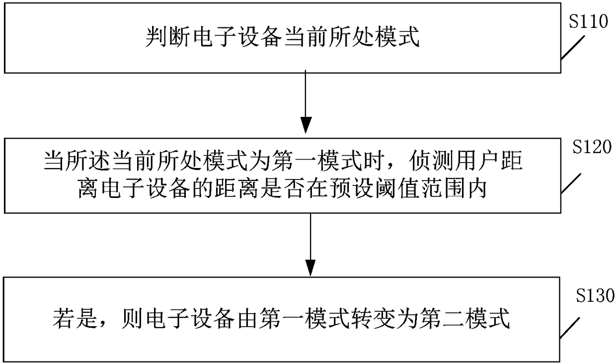
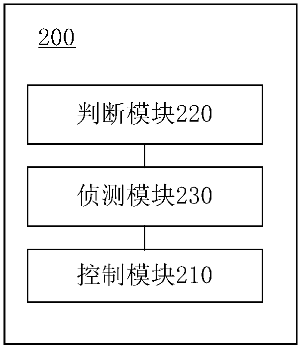
The invention provides an electronic equipment and a control method thereof. The control method comprises the following steps that: judging the current mode of the electronic equipment: when the current mode is a first mode, detecting whether a distance between a user and the electronic equipment is within a preset threshold value range or not, and if the distance between a user and the electronicequipment is within the preset threshold value range, converting the electronic equipment to a second mode from the first mode, wherein the first mode is the non-working mode of the electronic equipment, and the second mode is the working mode of the electronic equipment. By use of the control method, the electronic equipment can be intelligently switched among different control modes according to a user position.

Description

technical field [0001] The invention relates to the field of artificial intelligence, in particular to an electronic device and a control method thereof. Background technique [0002] Current electronic devices, especially smart electronic devices, when users want to activate them, they need to turn them on first to enter the login mode, and then the device can be activated by using iris, fingerprint, face, or password input, which is cumbersome to operate . For example, most computers are powered on, and then the user enters the password before the user can use the computer normally, which wastes the user's time and energy. In addition, in order to reduce the user's login operations, many notebook computers usually use face recognition technology for login operations, which makes the camera need to be in a standby state all the time, resulting in high power consumption of the notebook computer even when it is turned off. Contents of the invention [0003] The problem to...

Claims


Application Information

Patent Timeline
Patent Type & Authority Applications(China)
IPC IPC(8): G06F21/44
Inventor 秦桢肖启华莫志坚
Owner LENOVO (BEIJING) LTD
Learn More