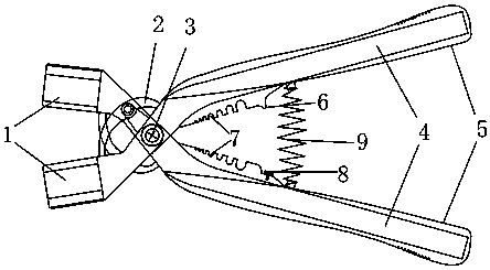
MC4 joint removal pliers for photovoltaic cable
A photovoltaic cable and clamp handle technology, applied in the direction of connection/disconnection of connecting devices, can solve the problems of inconvenient use, complex on-site environment of photovoltaic power plants, and difficult to effectively disassemble, etc., to reduce strength fatigue, facilitate effective application, and enhance convenience. Effect
- Summary
- Abstract
- Description
- Claims
- Application Information
AI Technical Summary
Problems solved by technology
Method used
Image

Examples
Embodiment Construction
[0044] In order to make the purpose, technical solutions and beneficial effects of the present invention more clear, the preferred embodiments of the present invention will be described in detail below in conjunction with the accompanying drawings, so as to facilitate the understanding of technical personnel. It should be understood that the embodiments described here are only used to illustrate and explain the present invention, and therefore the content of the specific examples should not limit the protection scope of the present invention.
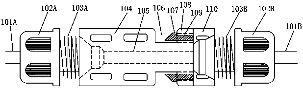
[0045] figure 1 In the figure, 101A and 101B are connecting wires at both ends of the connector, 102A and 102B are screw caps at both ends of the connector, 103A and 103B are threads at both ends of the street, and 104 is a female connector In the main structure, 105 is a matching metal terminal, 106 is a buckle groove, 107 is a buckle of a male joint, 108 is a rear end of a female joint, 109 is a buckle socket of a female joint, and 11...
PUM
 Abstract
Description
Claims
Application Information
 - R&D
- Intellectual Property
- Life Sciences
- Materials
- Tech Scout
- Unparalleled Data Quality
- Higher Quality Content
- 60% Fewer Hallucinations
Browse by: Latest US Patents, China's latest patents, Technical Efficacy Thesaurus, Application Domain, Technology Topic, Popular Technical Reports.
© 2025 PatSnap. All rights reserved.Legal|Privacy policy|Modern Slavery Act Transparency Statement|Sitemap|About US| Contact US: help@patsnap.com