Efficient compaction equipment for electric power engineering construction

A high-efficiency technology for power engineering, applied in the field of high-efficiency compaction equipment for power engineering construction, can solve the problems of high labor intensity, inability to compact the pole hole, and unsatisfactory compaction effect.

Inactive Publication Date: 2018-06-19
王珣
View PDF0 Cites 6 Cited by
  • Summary
  • Abstract
  • Description
  • Claims
  • Application Information

AI Technical Summary

Problems solved by technology

[0002] Electric power engineering, that is, projects related to the production, transmission and distribution of electric energy, also includes projects that use electricity as power and energy in various fields in a broad sense. Electricity has many advantages such as easy conversion, convenient transportation, easy control, convenient use, cleanliness and economy. Since the 1880s, electric power has gradually replaced the steam engine that was the technical basis of the industrial revolution in the 18th century, and has become the human being in modern society. The technical foundation of material civilization and spiritual civilization, the planning, design, construction and operation of electric power projects must pay attention to ensure the high reliability of power supply. Stability. The existing methods of tamping the ground or pole pits are mainly carried out manually, which is labor-intensive and cannot tamp the pole pits, and the tamping effect is not ideal. Therefore, we propose a high-efficiency tamping method for power engineering construction. equipment to solve the above problems

Method used


Image

  • Efficient compaction equipment for electric power engineering construction
  • Efficient compaction equipment for electric power engineering construction
  • Efficient compaction equipment for electric power engineering construction

Examples


Embodiment Construction

[0021] The following will clearly and completely describe the technical solutions in the embodiments of the present invention with reference to the accompanying drawings in the embodiments of the present invention. Obviously, the described embodiments are only some, not all, embodiments of the present invention.

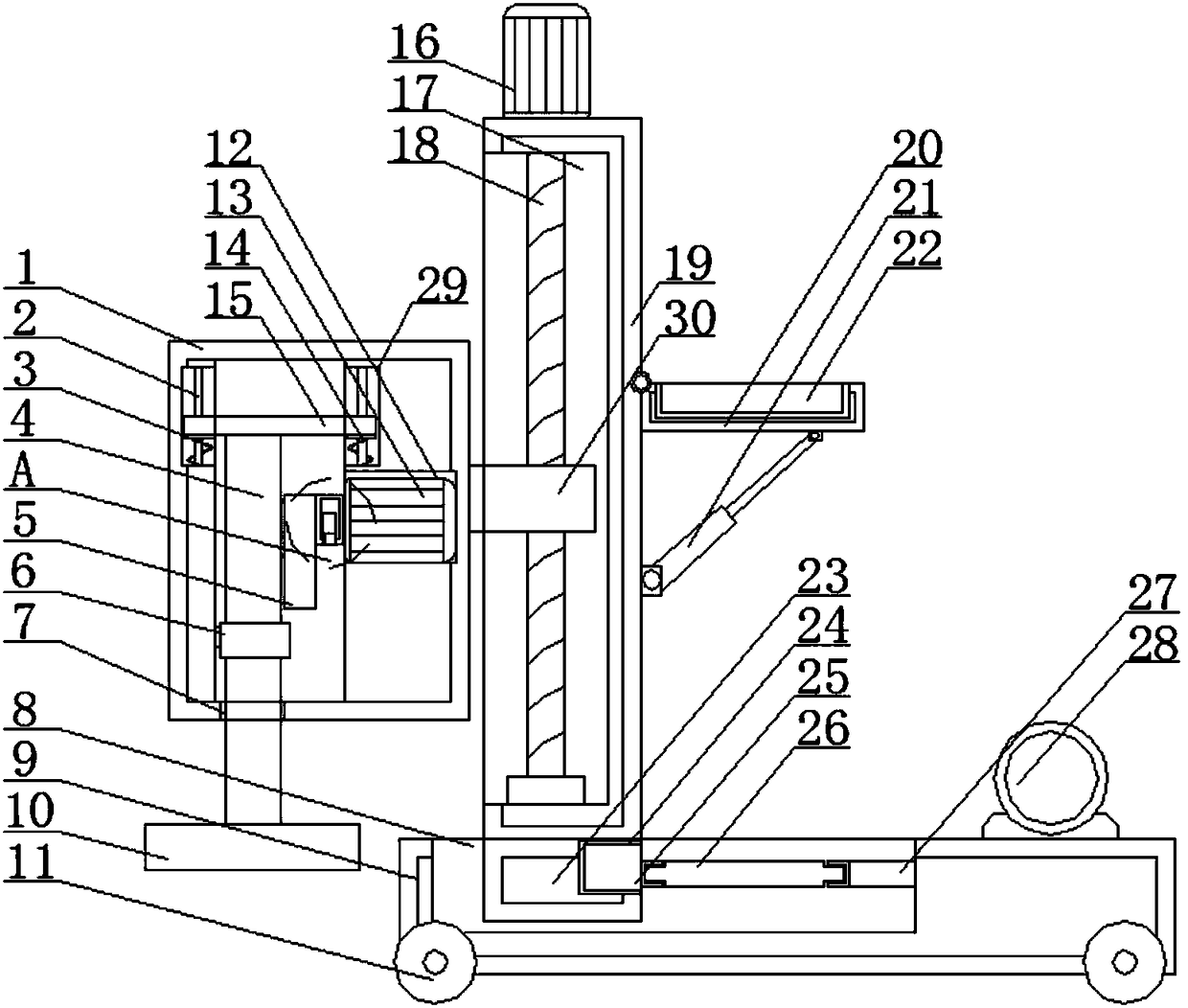
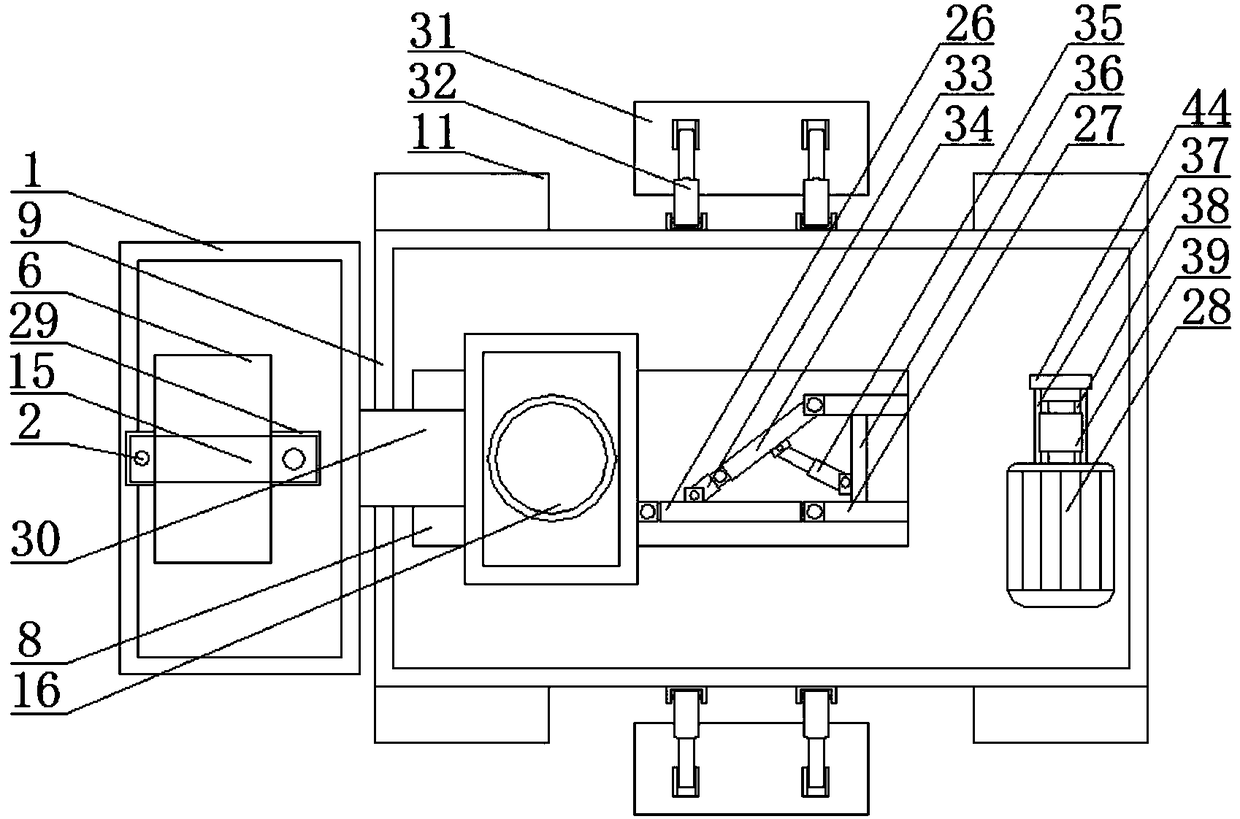
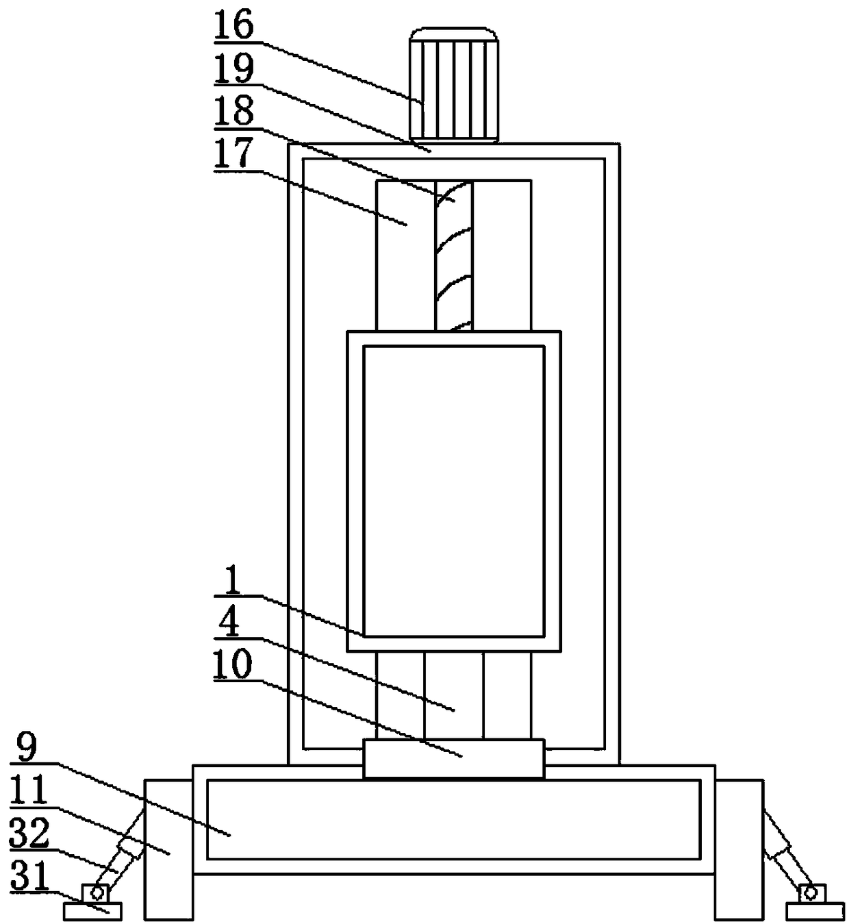
[0022] refer to Figure 1-5, a high-efficiency tamping equipment for power engineering construction, including a base plate 9, the lower end of the base plate 9 is provided with a walking device, which is convenient to move to a suitable position, both sides of the base plate 9 are provided with supporting devices for support, and the upper end of the base plate 9 is provided There is a first chute 8, and a moving device is arranged in the first chute 8, which is convenient for moving. The moving device is provided with a first slider 23, and the upper end of the first slider 23 is fixed with a moving block 19, which is convenient for the first slider to move. 23 dri...


PUM


Abstract

The invention discloses efficient compaction equipment for electric power engineering construction. The efficient compaction equipment for electric power engineering construction comprises a bottom plate; a walking device is arranged at the lower end of the bottom plate; supporting devices are arranged on the two sides of the bottom plate respectively; a first chute is arranged at the upper end ofthe bottom plate and is internally provided with a moving device; the moving device is provided with a first sliding block; the upper end of the first sliding block is fixed with a moving block; anda bearing device is arranged on one side of the moving block. The efficient compaction equipment provided by the invention realizes convenient compaction on the ground or a pole pit in the electric power engineering construction process, solves the problems that the labor intensity is large, the pole pit cannot be compacted, and the compaction effect is ideal during manual compaction on the groundor the pole pit through a combination of a driving device, a rotary plate, a press block and a thread rod, is high in automatic degree, reduce the labor intensity of the constructors, is high in working efficiency and compaction effect, improves the engineering construction progress, ensures the engineering quality, is simple in structure and convenient to operate and is suitable for popularization.

Description

technical field [0001] The invention relates to the technical field of electric power engineering, in particular to a high-efficiency compaction device for electric power engineering construction. Background technique [0002] Electric power engineering, that is, projects related to the production, transmission and distribution of electric energy, also includes projects that use electricity as power and energy in various fields in a broad sense. Electricity has many advantages such as easy conversion, convenient transportation, easy control, convenient use, cleanliness and economy. Since the 1880s, electric power has gradually replaced the steam engine that was the technical basis of the industrial revolution in the 18th century, and has become the human being in modern society. The technical foundation of material civilization and spiritual civilization, the planning, design, construction and operation of electric power projects must pay attention to ensure the high reliabi...

Claims


Application Information

Patent Timeline
Patent Type & Authority Applications(China)
IPC IPC(8): E02D3/046E04H12/34
CPCE02D3/046E04H12/347
Inventor 王珣孙刚王慧超
Owner 王珣
Why Eureka
Try Eureka