Air exchanging device

An air displacement and hole technology, which is applied in airflow control elements, space heating and ventilation, space heating and ventilation details, etc. Effect

Inactive Publication Date: 2018-06-19
甘肃秦洁环境科技有限公司
View PDF0 Cites 0 Cited by
  • Summary
  • Abstract
  • Description
  • Claims
  • Application Information

AI Technical Summary

Problems solved by technology

[0002] The existing air replacement device cannot perform simple dust adsorption treatment, which easily affects the quality of indoor control

Method used


Image

  • Air exchanging device
  • Air exchanging device

Examples


Embodiment Construction

[0010] In order to make the object, technical solution and advantages of the present invention more clear, the present invention will be further described in detail below in conjunction with the examples.

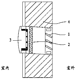
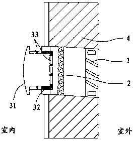
[0011] refer to Figure 1~2 As shown, the present invention discloses an air replacement device, which is installed on the outer wall 4 with holes reserved, and includes a shunt grid 1 , a dust filter 2 and a control switch 3 .

[0012] The radius of the reserved hole is set to 100-150mm, and the inner side of the reserved hole is inclined downward to the outer side, and the inclination angle is 5°-10°. The reserved holes are set downwards to make it easier for the air to flow from the outside to the inside.

[0013] The shunt grid 1 is made of aluminum alloy, and it is arranged on the outside of the reserved hole. The control switch 3 is made of hard PVC plastic material and is located inside the reserved hole. The control switch 3 is composed of a pressing part 31 and ...


PUM


Abstract

The invention discloses an air exchanging device. The air exchanging device is arranged on an outer wall body which is provided with a hole in advance; the air exchanging device comprises a flow dividing grid plate, a dust collecting filter screen and a control switch; the flow dividing grid plate is arranged at the outer side of the pre-formed hole; the control switch is positioned at the inner side of the pre-formed hole; and the dust collecting filter screen is positioned at the middle of the pre-formed hole. The air exchanging device disclosed by the invention is simple in structure and can realize supply of natural fresh air from an outdoor place to an indoor place in a low energy consumption manner.

Description

technical field [0001] The invention relates to the technical field of fresh air systems, in particular to an air replacement device. Background technique [0002] The existing air replacement device cannot perform simple dust adsorption treatment, which easily affects the quality of indoor control. Contents of the invention [0003] The purpose of the present invention is to provide an air replacement device to realize the supply of natural fresh air from the outside of the space to the inside of the space with low energy consumption. [0004] To achieve the above object, the present invention adopts the following technical solutions: [0005] An air replacement device, which is installed on an outer wall with holes reserved, and includes a diversion grid, a dust filter and a control switch. The diversion grid is located outside the reserved hole, and the control switch is located Inside the reserved hole, the dust removal filter is located in the middle of the reserved...

Claims


Application Information

Patent Timeline
Patent Type & Authority Applications(China)
IPC IPC(8): F24F7/00F24F13/28F24F13/08
CPCF24F7/00F24F13/082F24F13/28F24F2007/0025
Inventor 蒋尉平
Owner 甘肃秦洁环境科技有限公司
Why Eureka
Try Eureka