
Optical fiber connector and method for assembling same

A technology of an optical fiber connector and an assembling method, which is applied in the field of communication, can solve the problems such as the inability to realize optical fiber docking, and achieve the effects of simple structure, convenient installation and low cost.

Active Publication Date: 2018-06-22
GUANGXUN SCI & TECH WUHAN
View PDF4 Cites 8 Cited by
  • Summary
  • Abstract
  • Description
  • Claims
  • Application Information

AI Technical Summary

Problems solved by technology

Therefore, in this case, the traditional connector scheme cannot realize the butt joint between optical fibers

Method used


Image

  • Optical fiber connector and method for assembling same
  • Optical fiber connector and method for assembling same
  • Optical fiber connector and method for assembling same

Examples


Embodiment 1

[0042] What the present invention proposes is a design idea of ​​a connector, which can be applied to various types of connectors that are common at present, such as SC type, LC type, ST type, etc. Take the structure as an example, and further illustrate how the present invention is realized in conjunction with the accompanying drawings.

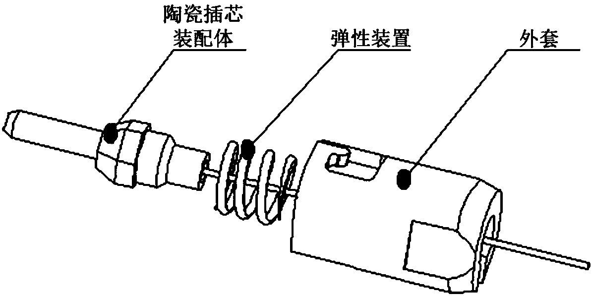
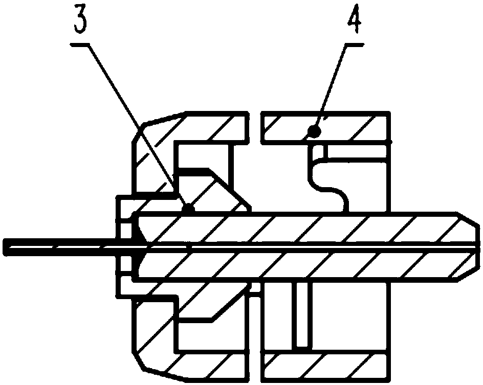
[0043] Such as figure 2 As shown, an optical fiber connector provided by Embodiment 1 of the present invention includes a jacket 4 and a ferrule assembly 3, the jacket 4 is a hollow structure, and the ferrule assembly 3 is arranged in the hollow structure of the jacket 4;

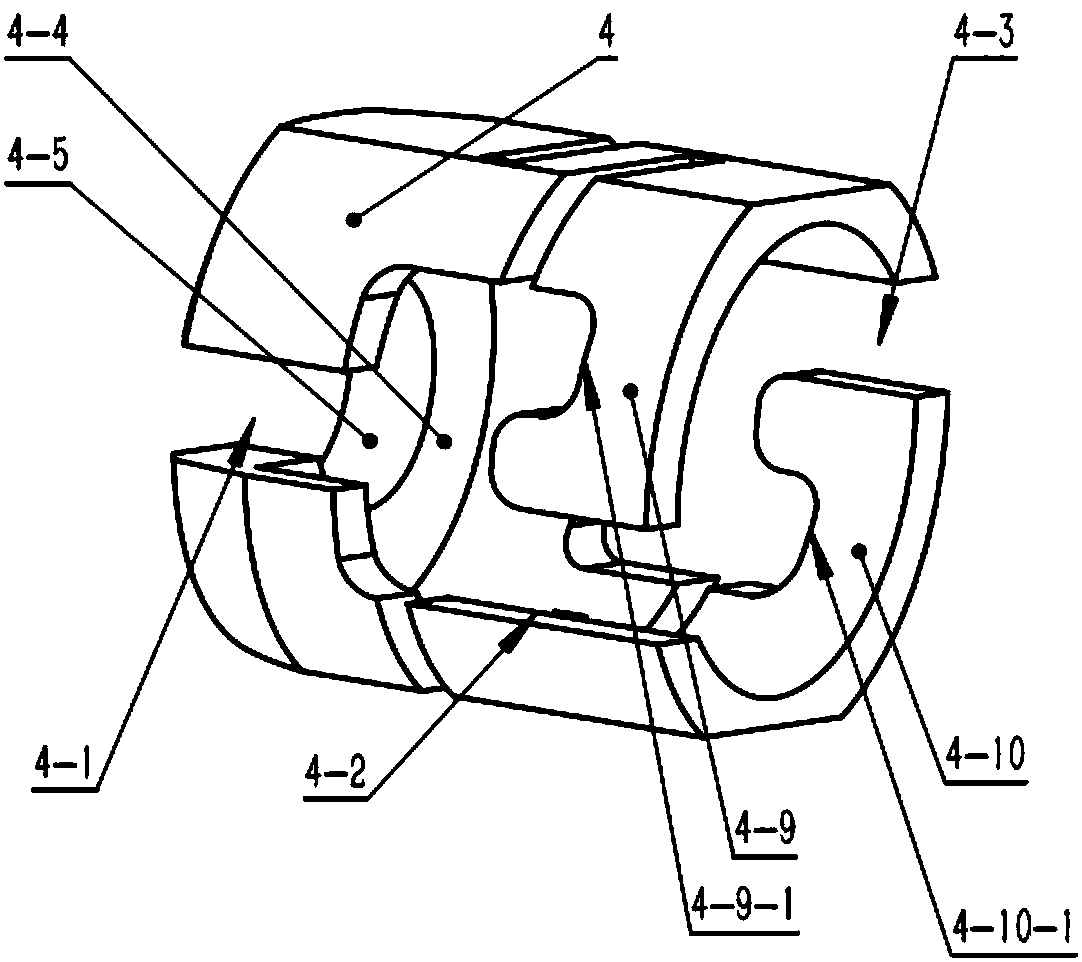
[0044] The outer wall of the jacket 4 is provided with a left open groove 4-2 and a right open groove 4-3, and the left open groove 4-2 and the right open groove 4-3 are circumferentially symmetrical with respect to the central axis of the jacket 4;

[0045] Described overcoat 4 also comprises upper deformation groove 4-7, lower deformation groove 4-6, deformation bridge ...

Embodiment 2

[0057] This embodiment 2 is based on the embodiment 1, uses the above-mentioned optical fiber connector and its adapter, and uses the example of the butt coupling of the two to describe the assembly method of the connector of the present invention in detail, including: the ferrule assembly 3 first and the corresponding The adapter is pre-assembled, and the jacket 4 is then assembled with the corresponding adapter; during the assembly process of the jacket 4 and the corresponding adapter, the jacket 4 assembles the ferrule through the through channel of its pigtail groove 4-1 and the left open groove 4-2 The body 3 enters the inner cavity of the jacket 4, and then completes the assembly with the ferrule assembly 3.

[0058] Compared with the traditional assembly method, the assembly method of the optical fiber connector provided by the present invention can realize reverse assembly, allowing the parts that make up the connector to be placed in a small space in batches, and then ...


PUM


Abstract

The invention relates to the field of communication, and provides an optical fiber connector and a method for assembling the same. The optical fiber connector comprises a jacket and an insertion coreassembly. The jacket is of a hollow structure, and the insertion core assembly is arranged in the hollow structure of the jacket; a left open groove and a right open groove are formed in the wall of the jacket and are symmetric with each other relative to the circumference of the central axis of the jacket; the jacket further comprises upper deformation grooves, lower deformation grooves, deformation bridges, a left movable portion and a right movable portion, the upper deformation grooves and the lower deformation grooves which are adjacent to one another are connected with one another by thedeformation bridges, and the left movable portion and the right movable portion are connected with a jacket body by the deformation bridges; the deformation bridges are made of elastic materials. Theoptical fiber connector and the method have the advantages that elastic devices are directly integrated with shells, and the optical fiber connector is simple in structure, convenient to mount and low in cost and is in miniaturization designs; the optical fiber connector is assembled in inverted order, and accordingly the optical fiber connector and adapters can be smoothly coupled and mounted even in places with coupling spaces smaller than the size of the optical fiber connector.

Description

【Technical field】 [0001] The invention relates to the communication field, in particular to an optical fiber connector and an assembly method thereof. 【Background technique】 [0002] The connection between optical fiber and optical fiber, and the connection between optical fiber and equipment are basically realized through connectors. With the explosive growth of the information Internet, the requirements for optical fiber connection density are also continuously increasing, that is, within a unit volume To achieve more optical fiber connections. In those optical modules that require high-density connection of optical paths and some optical modules with very limited space, a small-sized connector that is smaller in length and cross-sectional area than conventional connectors and is easy to install and operate is very necessary. Usually, some R&D engineers shorten the sheath of common connectors, or directly couple two ceramic ferrules and dispense glue to achieve small-size...

Claims


Application Information

Patent Timeline
IPC IPC(8): G02B6/38
CPCG02B6/3825
Inventor 赵小博杨宇翔全本庆胡毅
Owner GUANGXUN SCI & TECH WUHAN
Learn More