
Face recognition device for construction site

A technology for face recognition equipment and construction sites, applied in the direction of use feedback control, etc., can solve problems such as reduced practicality and reliability of face recognition equipment, damage to circuit components of face recognition cameras, and blurred images captured by cameras. Achieve the effects of improving practicability and reliability, expanding the scope, and improving the effect of recognition

Inactive Publication Date: 2018-06-22
小视科技(江苏)股份有限公司
View PDF0 Cites 5 Cited by
  • Summary
  • Abstract
  • Description
  • Claims
  • Application Information

AI Technical Summary

Problems solved by technology

[0003] With the development of science and technology, face recognition technology has been widely used in various fields of life, such as face recognition cameras used on construction sites. Although face recognition cameras can quickly perform identity verification and improve work efficiency, However, in the process of actual use, there are still some deficiencies in the face recognition cameras used on construction sites. The existing face recognition cameras are basically fixedly installed on the wall, which leads to a limited recognition range and requires people to stand on the camera. Face recognition can only be realized by aligning with the front, which is inconvenient, and once many people pass by the camera at the same time, there may be incomplete recognition, which reduces the practicability of the camera. In addition, due to the large amount of dust on the construction site, the camera will , Dust will accumulate on the lens, making the image captured by the camera blurred, causing recognition problems, and in summer, due to the high outdoor temperature, the high temperature will cause damage to the circuit components inside the face recognition camera, thus affecting the normal operation of the device. Reduced the practicality and reliability of face recognition equipment

Method used


Image

  • Face recognition device for construction site
  • Face recognition device for construction site
  • Face recognition device for construction site

Examples


Embodiment Construction

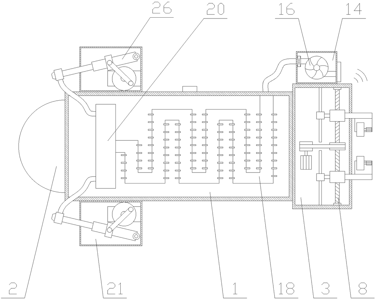
[0028] The present invention is described in further detail now in conjunction with accompanying drawing. These drawings are all simplified schematic diagrams, which only illustrate the basic structure of the present invention in a schematic manner, so they only show the configurations related to the present invention.

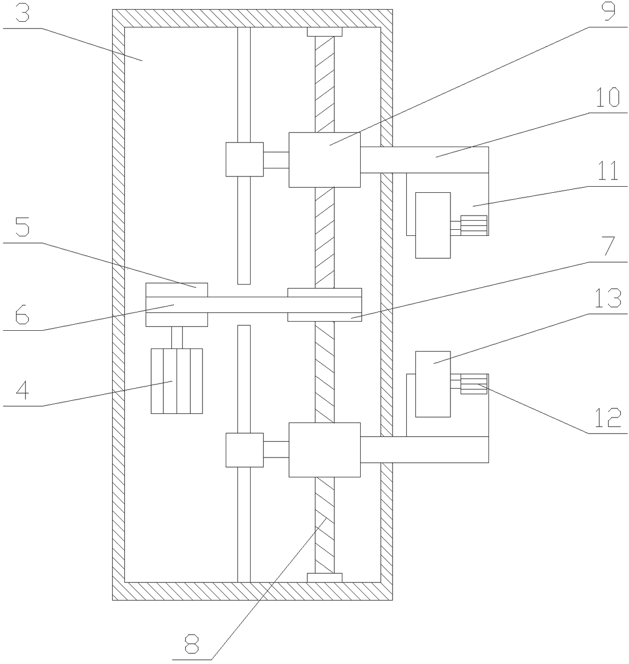
[0029] Such as figure 1 As shown, a face recognition device for a construction site includes a main body 1 and a camera 2, and also includes a moving mechanism and a processing mechanism. The camera 2 is set on one side of the main body 1, and the moving mechanism is set on the main body 1. The side away from camera 2;

[0030] Through the moving mechanism, the main body 1 and the guide rail can be easily installed and disassembled, and by moving on the guide rail, the camera 2 can be scanned in matrix, which expands the scanning range and uploads to the computer through continuous data collection Perform comparison calculations to obtain more accurate compa...


PUM


Abstract

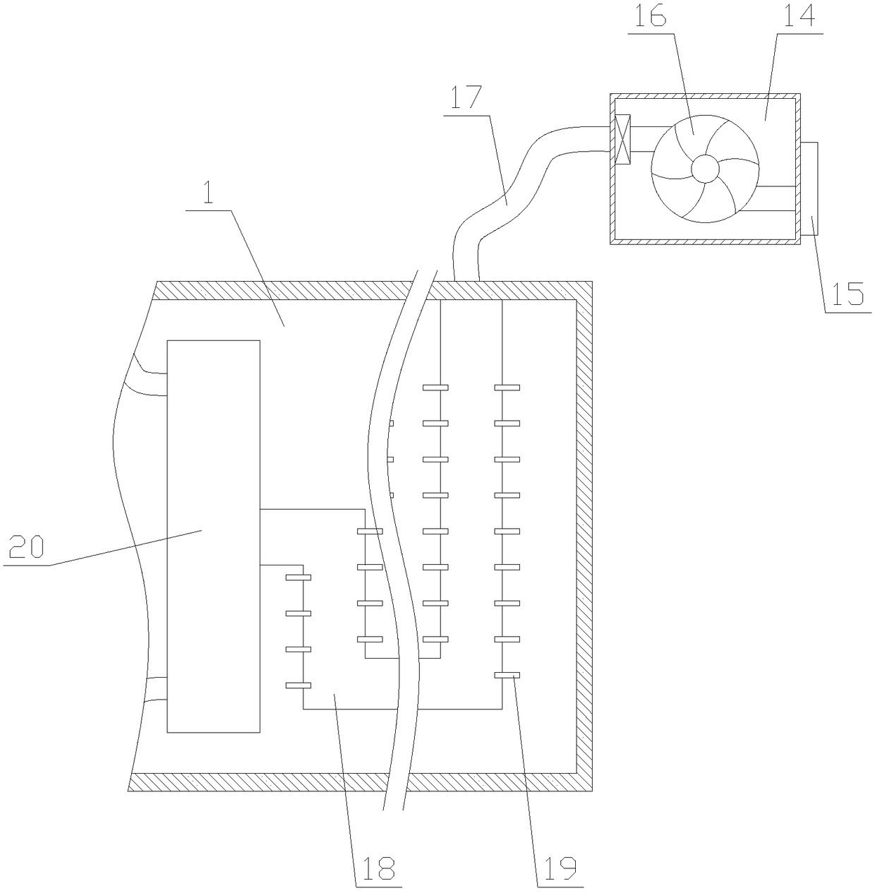
The invention relates to a face recognition device for a construction site. The device comprises a main body and a camera, and further comprises a moving mechanism and a processing mechanism, the moving mechanism comprises a shell, a control assembly and a moving assembly, and the processing mechanism comprises a heat dissipation assembly and a dust removal assembly. The face recognition device for the construction site uses the moving mechanism to facilitate installation and disassembly between a main body and a guide rail, enables the camera to perform matrix scanning, expands the scanning range, and continuously collects data, compares and calculates to obtain a more accurate comparison result, the face recognition is more comprehensive, through the processing mechanism, the inside of the main body can be cooled so that the face recognition device can work normally and stably, the dust and ice layers on the surface of the camera are removed, scanning images are clearer, the recognition effect is improved, and the practicality and reliability of the face recognition device are improved.

Description

technical field [0001] The invention relates to the field of face recognition, in particular to a face recognition device used in a construction site. Background technique [0002] Face recognition is a biometric technology for identification based on human facial feature information. A series of related technologies that use a video camera or camera to collect images or video streams containing human faces, automatically detect and track human faces in the images, and then perform facial recognition on the detected faces, usually also called portrait recognition and facial recognition. [0003] With the development of science and technology, face recognition technology has been widely used in various fields of life, such as face recognition cameras used on construction sites. Although face recognition cameras can quickly perform identity verification and improve work efficiency, However, in the process of actual use, there are still some deficiencies in the face recognitio...

Claims


Application Information

Patent Timeline
Patent Type & Authority Applications(China)
IPC IPC(8): G05D3/20
CPCG05D3/20
Inventor 杨帆陈兰
Owner 小视科技(江苏)股份有限公司
Learn More