
Tunnel access control device

A technology for access control and tunnels, which is applied in the field of tunnel access control devices, can solve the problem that the length of the blocking device cannot be too long, and achieve the effect of reducing the driving force

Active Publication Date: 2018-06-26
CHINA FIRST HIGHWAY ENG +1
View PDF5 Cites 4 Cited by
  • Summary
  • Abstract
  • Description
  • Claims
  • Application Information

AI Technical Summary

Problems solved by technology

[0003] The object of the present invention is to provide a tunnel access control device to improve the problem that the length of the blocking device cannot be too long

Method used


Image

  • Tunnel access control device
  • Tunnel access control device
  • Tunnel access control device

Examples


Embodiment 1

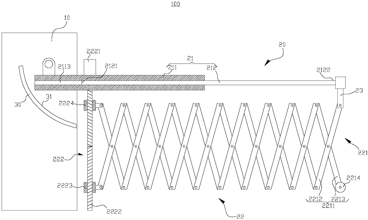
[0044] Such as figure 1 As shown, the present embodiment provides a tunnel access control device 100 , including a support base 10 , a blocking device 20 and an abutting member 30 , and the blocking device 20 includes a blocking member 21 and a driving mechanism 22 .

[0045] Wherein, the support seat 10 is a cuboid structure, which plays a role in supporting various components.

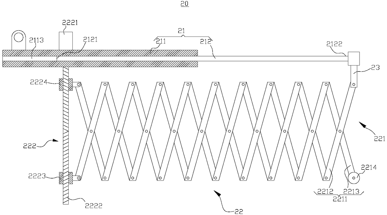
[0046] Such as figure 2 As shown, the blocking member 21 includes a fixed body 211 and a movable body 212 , the movable body 212 is movably connected with the fixed body 211 , and the movable body 212 can move axially relative to the fixed body 211 to make the blocking member 21 extend or shorten.

[0047] Among them, such as image 3 As shown, the fixed body 211 includes a rod part 2111 and a support part 2112 , one end of the support part 2112 is connected and fixed to the rod part 2111 , and the support part 2112 is perpendicular to the rod part 2111 . Wherein, the rod portion 2111 is provided...

Embodiment 2

[0061] This embodiment provides a tunnel access control device 100 , which is different from the above embodiments in that the structure of the abutting member 30 is different.

[0062] In this embodiment, the abutment member 30 is a gear 40 , and the movable body 212 in the blocking member 21 has a toothed portion 2123 , that is, the movable body 212 is a rack structure. The cross section of the movable body 212 is rectangular, and the cross section of the through hole 2113 in the fixed body 211 is also rectangular. The movable body 212 can move along a fixed track after being set in the through hole 2113 in the fixed body 211 .

[0063] The gear 40 is fixed on the support base 10 , the axis of the gear 40 coincides with the rotation axis of the fixed body 211 relative to the support base 10 , and the toothed part 2123 of the movable body 212 can mesh with the gear 40 during the shortening process of the blocking member 21 . Before the gear 40 meshes with the toothed part 212...


PUM


Abstract

The invention provides a tunnel access control device, and belongs to the technical field of tunnel safety. The tunnel access control device includes a supporting base, a blocking device and an abutting member. The blocking device includes a blocking member and a driving mechanism. The blocking member comprises a fixed body and a moving body, the fixed body is rotatably connected with the supporting base, and the moving body can move relative to the fixed body to enable the blocking member to extend or shorten. The driving mechanism is used for driving the moving body to move relative to the fixed body. The abutting member is fixed to the supporting base, and when the moving body moves relative to the fixed body to enable the blocking member to shorten, the moving body can be in contact with the abutting member to push the fixed body to rotate upwards relative to the supporting base. When the tunnel access control device is opened, the center of gravity of the blocking device is movedback, so that the blocking device is ensured to be with a sufficient length at the blocking position, and the driving force required for the blocking device to rotate upwards is reduced.

Description

technical field [0001] The invention relates to the technical field of tunnel safety, in particular to a tunnel access control device. Background technique [0002] During tunnel construction, tunnel access control devices are often installed at the entrance and exit of the tunnel to prevent vehicles from entering. Existing tunnel access control devices generally consist of a support base, a blocking device and a motor. The blocking device is rotatably connected to the support base, and the motor is used to drive the blocking device to rotate. The length of the blocking device in the existing access control device cannot be too long, and the motor cannot drive it to rotate if it is too long. Due to the large width of the tunnel, two access control devices are generally arranged at the tunnel entrance. Contents of the invention [0003] The purpose of the present invention is to provide a tunnel access control device to improve the problem that the length of the blocking ...

Claims


Application Information

Patent Timeline
IPC IPC(8): E01F13/04E01F13/06
CPCE01F13/048E01F13/06
Inventor 刘方华陈胜亮李东坡赵钊庞秋阳陈秀谨
Owner CHINA FIRST HIGHWAY ENG
Learn More