Contact support reaction spring installing structure and assembling method

A technology of reaction force spring and contact support, applied in the direction of detailed information of electromagnetic relays, relays, electrical components, etc., can solve the problems of difficulty in production, troublesome deburring of parts, high requirements for manufacturing precision and matching precision, and reduce the difficulty of production , the effect of improving production efficiency

Active Publication Date: 2016-10-05
XIAMEN HONGFA ELECTRICAL SAFETY & CONTROLS CO LTD
View PDF5 Cites 3 Cited by
  • Summary
  • Abstract
  • Description
  • Claims
  • Application Information

AI Technical Summary

Problems solved by technology

[0004] 1. Before positioning, the reaction force spring must enter the boss 100 supported by the contact through interference fit, which is not convenient for automatic line assembly;
[0005] 2. Since the root of the contact support boss 100 needs to be provided with a groove 101, there are joints in the mold, which makes the production difficult, and the deburring of the parts is also very troublesome;
[0006] 3. Since the root of the contact support boss needs to be provided with a groove 101, the groove is too large, the positioning is unstable, and the spring is not in place if the groove is small, so that the manufacturing precision and matching precision are required to be high, which increases the difficulty of production;
[0007] 4. Since the root of the contact support boss needs to be provided with a groove 101, the boss supported by the contact must have a certain length, which is restricted by the total stroke of the contactor (when the reaction force spring is compressed, the contact support The boss and the positioning boss of the coil bobbin will be close to each other), which will make the length of the positioning boss of the coil bobbin not long enough, reduce the guiding effect of the positioning boss of the coil bobbin, and affect the assembly speed of the product;
[0008] 5. Since the root of the contact support boss needs to be provided with a groove 101, the size of the boss 100 cannot be too small, and due to the setting of the relief part 102 (required for core pulling in the production process), the hook 103 supported by the contact will The thickness of the wall 104 is thinned, thereby affecting the strength of the hook 103

Method used


Image

  • Contact support reaction spring installing structure and assembling method
  • Contact support reaction spring installing structure and assembling method
  • Contact support reaction spring installing structure and assembling method

Examples


Embodiment

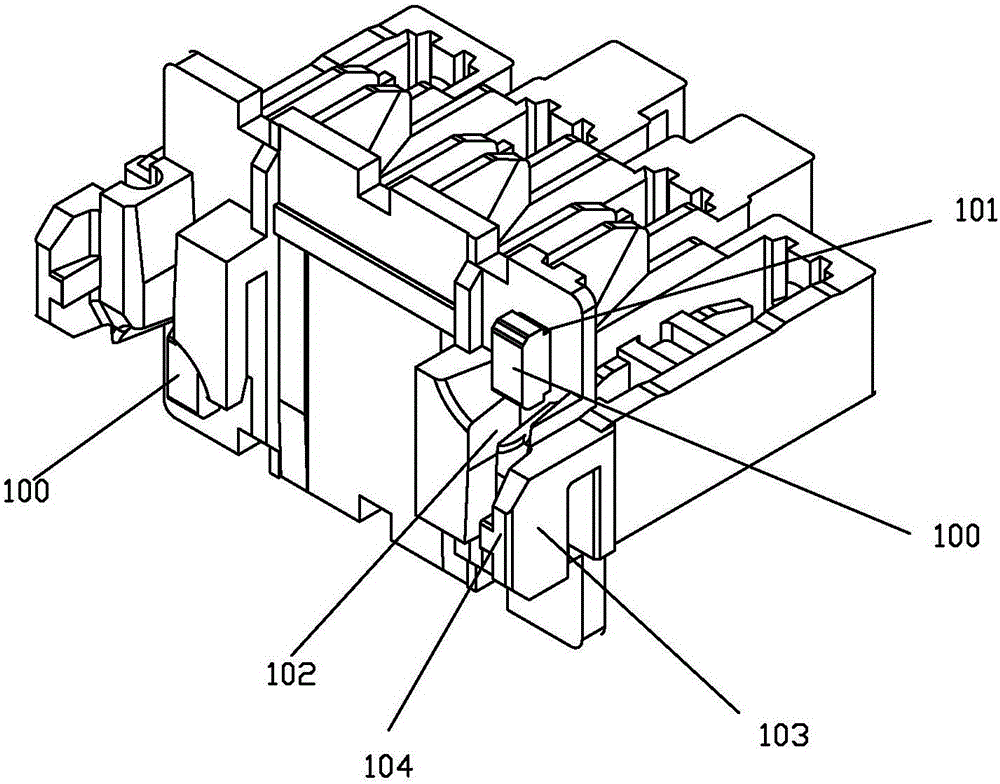
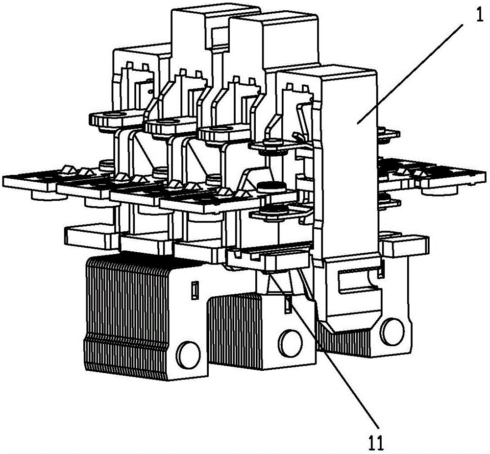
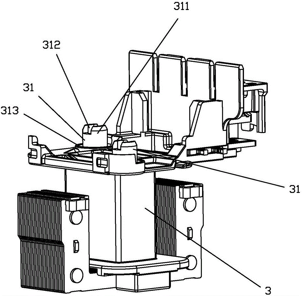
[0033] see Figure 2 to Figure 12 As shown, a contact support and reaction force spring installation structure of the present invention includes a contact support 1, a reaction force spring 2 and a coil frame 3; The first boss 11 of the bobbin 3 is provided with a second boss 31 used to match the other end of the reaction force spring 2; the protrusion of the second boss 31 has a raised portion 311, so that The reaction force spring can utilize the small gap of the mode of self free fall to be sleeved on the second boss 31 that has sufficient length and is convenient for guiding; When the first boss 11 supported by the contact overlaps with the second boss 31 of the bobbin due to being compressed, the avoidance portion 312 of the second boss forms an overlapping portion of the first boss 11 supported by the contact. Avoidance, so that the total stroke set by the contactor remains unchanged.

[0034] In this embodiment, the cross-section of the first boss 11 supported by the ...


PUM


Abstract

The invention discloses a contact support reaction spring installing structure and assembling method. The installing structure comprises a contact support, a reaction spring and a coil bobbin. The contact support is provided with a first boss which is used for being matched with one end of the reaction spring. The coil bobbin is provided with a second boss which is used for being matched with the other end of the reaction spring. The protrusion of the second boss is provided with a heightening part so that the reaction spring is enabled to be sleeved on the second boss which is sufficient in length and convenient for guiding by utilizing the mode of free falling of itself in a small clearance way. The heightening part of the second boss is provided with an avoiding part. When the reaction spring is compressed and the first boss of the contact support and the second boss of the coil bobbin are enabled to be overlapped, the avoiding part of the second boss forms avoidance for the overlapping part of the first boss of the contact support, and the set total stroke of a contactor is enabled to be unchanged. The manufacturing difficulty can be effectively reduced, automatic line assembling can be conveniently realized, and the guiding effect of the positioning boss of the coil bobbin can also be increased so that assembling speed can be enhanced.

Description

technical field [0001] The invention relates to the technical field of contactors, in particular to an installation structure and an assembly method of a contact support and reaction force spring. Background technique [0002] A contactor refers to an electrical appliance that uses a coil to flow current to generate a magnetic field in industrial electricity to close the contacts to control the load. [0003] A contactor in the prior art is equipped with a reaction force spring between the contact support and the coil bobbin, as disclosed in the Chinese patent application publication number CN104064383A, the installation structure of this reaction force spring is a contact support Form the deck 100 on the end face (such as figure 1 As shown), that is, a boss structure is formed, and a card groove 101 is formed on the card seat 100, that is, a groove is formed at the root of the boss. When installing, one end of the reaction force spring must enter the contact support boss 1...

Claims


Application Information

Patent Timeline
Patent Type & Authority Applications(China)
IPC IPC(8): H01H50/44H01H50/56H01H49/00
CPCH01H49/00H01H50/44H01H50/56H01H2050/446
Inventor 晏恒明曹永徐颖翔
Owner XIAMEN HONGFA ELECTRICAL SAFETY & CONTROLS CO LTD
Why Eureka
Try Eureka