
An oiling device with reciprocating motion

A movement mode and reciprocating technology, applied in the direction of coating, liquid coating device on the surface, etc., can solve the problems of lubricating oil dripping, manual erasing, increasing the workload of staff, etc., to reduce vibration and avoid Effects of rework and service life extension

Active Publication Date: 2019-07-05
东港智科产业园有限公司
View PDF5 Cites 0 Cited by
  • Summary
  • Abstract
  • Description
  • Claims
  • Application Information

AI Technical Summary

Problems solved by technology

[0005] The object of the present invention is to provide a reciprocating motion oiling device, through the power of the positioning cylinder, the push block is driven to move upward, and the cooperation between the guide rod and the guide hole avoids misalignment or deviation from the predetermined track when the push block moves Possibility, realize the advantages of precise positioning of the vehicle, and solve the problem that the fuel tank is fixed directly above the vehicle. When oiling, it may cause lubricating oil to drip onto the product, and finally the oil drop needs to be manually wiped off , which increases the workload of the staff

Method used


Image

  • An oiling device with reciprocating motion
  • An oiling device with reciprocating motion
  • An oiling device with reciprocating motion

Examples


Embodiment Construction

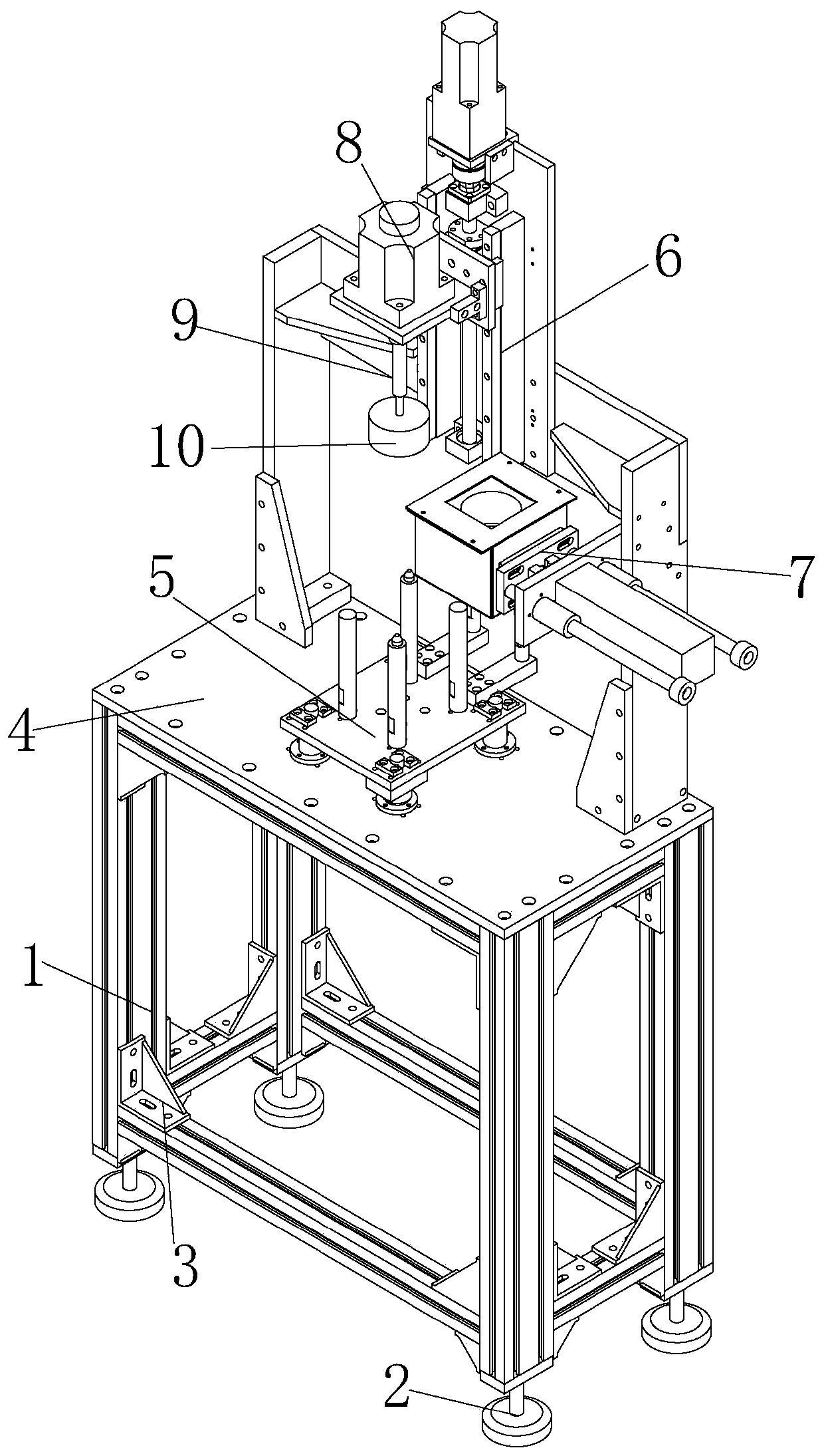
[0026] The technical solutions in the embodiments of the present invention will be clearly and completely described below in conjunction with the accompanying drawings in the embodiments of the present invention. Obviously, the described embodiments are only a part of the embodiments of the present invention, rather than all the embodiments. Based on the embodiments of the present invention, all other embodiments obtained by those of ordinary skill in the art without creative work shall fall within the protection scope of the present invention.

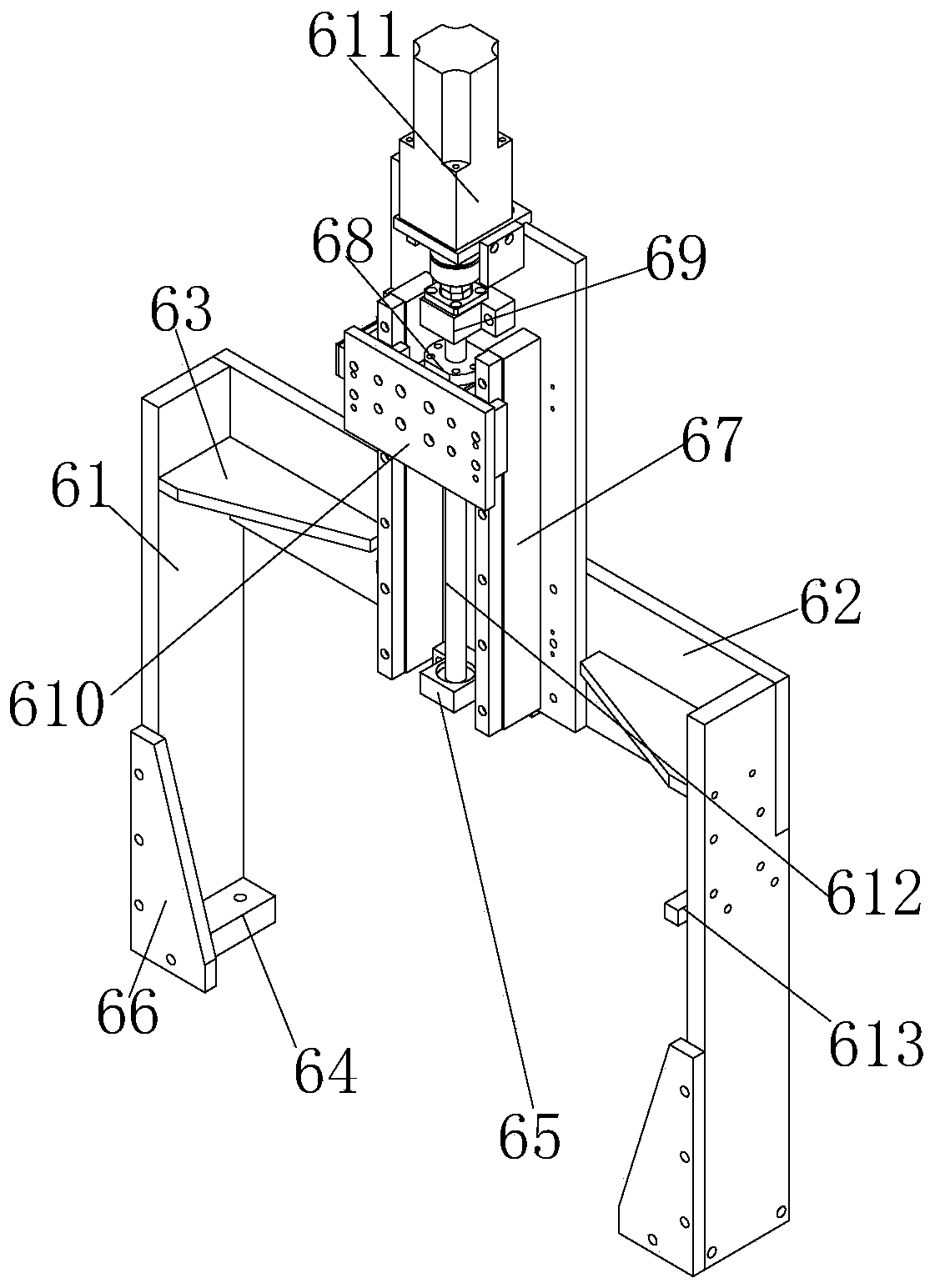
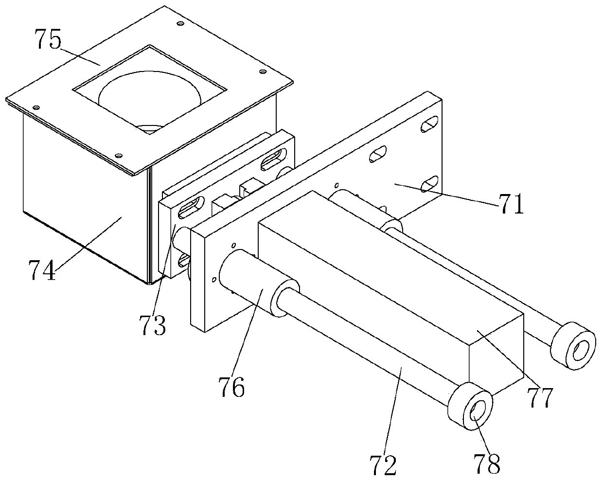
[0027] Reference Figure 1-5 , An oiling equipment with reciprocating motion, including a frame 1, a base 2 is provided on the four sides of the bottom of the frame 1, and the inner corners of the frame 2 are fixed with reinforcing ribs 3 by fixing bolts. 1 A flat plate 4 is provided at the top, a positioning mechanism 5 is provided in the middle of the flat plate 4, and the positioning mechanism 5 includes a push block 51. The four side...


PUM


Abstract

The invention discloses oil coating equipment with a reciprocating movement mode. The oil coating equipment comprises a machine frame, wherein bases are arranged at four sides of the bottom end of themachine frame; the inner side edge positions of the machine frame are fixedly provided with reinforcing bars through fixing screw bolts; the top end of the machine frame is provided with a flat plate; a positioning mechanism is arranged in the middle part of the flat plate and comprises a push block; guide rods are arranged at the four sides of the bottom end of the push block; the bottom ends ofthe four guide rods are arranged in guide holes formed in the flat plate; the top ends of the guide rods penetrate through the push block; press blocks are arranged at the two sides of the guide rodsand the push block; a positioning air cylinder is arranged in the middle part of the bottom end of the push block. Through a positioning mechanism arranged in the equipment, the push block is drivento upwards move through a power of the positioning air cylinder; the guide rods and the guide holes are matched; the possibility of the push block for generating position staggering or deviating froma preset track during the movement can be avoided; the support posts achieve good support effects; in addition, auxiliary support elements can support and limit the movement position of the movement plate; the precise positioning of a carrier is realized.

Description

Technical field [0001] The invention relates to the technical field of oil injection devices, in particular to an oil application equipment with a reciprocating motion mode. Background technique [0002] In the process of production and processing, it is often necessary to apply oil to the parts. At present, most of the oiling operations are carried out by manual oil guns to oil the parts. Even if the equipment is used for oiling operations, when targeting light and thin products, It is easy to cause the oil injection needle to collide with the product during oil injection and cause the product to shift, which makes it impossible to apply the oil to the precise position during subsequent oil application. As a result, the oil application operation fails and requires manual remedy, which is very inconvenient. [0003] After searching, the Chinese Patent Grant No. CN 206083008 U discloses oiling equipment, which mainly includes a product placement carrier and a carrier drive mechanism...

Claims


Application Information

Patent Timeline
Patent Type & Authority Patents(China)
IPC IPC(8): B05C1/06B05C11/10B05C11/00
CPCB05C1/06B05C11/00B05C11/10
Inventor 何涛
Owner 东港智科产业园有限公司
Learn More