Power cable bender and method of use

A power cable and bender technology, applied in the field of power cable benders, can solve the problems of inconvenient carrying, inconvenient threading and safety hazards, etc., and achieve the effect of being convenient to carry

Active Publication Date: 2020-01-21
DEZHOU POWER SUPPLY COMPANY OF STATE GRID SHANDONG ELECTRIC POWER +2
View PDF11 Cites 0 Cited by
  • Summary
  • Abstract
  • Description
  • Claims
  • Application Information

AI Technical Summary

Problems solved by technology

[0003] The present invention is a power cable bender and its use method, aiming to improve the problems existing in the current steel wire bender such as inconvenient carrying, inconvenient threading and potential safety hazards.

Method used


Image

  • Power cable bender and method of use

Examples


Embodiment 1

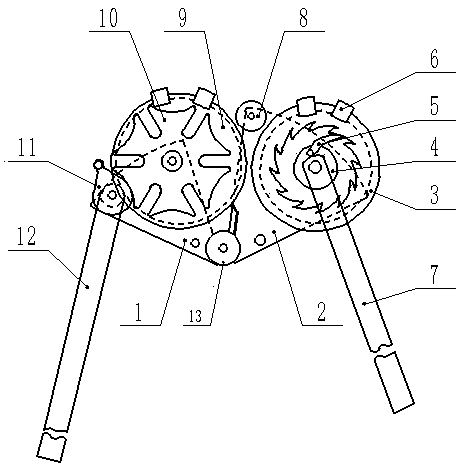
[0024] The invention is a power cable bender, as attached figure 1 As shown, a power cable bender includes a support plate A1, and the lower ends of the support plate A1 and the support plate B2 are overlapped and fixedly connected to each other, and an angle adjustment device 13 is arranged at the connection, and the angle adjustment device 13 may include an adjustment knob , the adjustment knob is stepped, the head of the adjustment knob is a grip part, the lower part of the grip part is connected with a cylinder concentric with the grip part, the cylinder is provided with a tooth part, and the tooth The lower end of the part is a rotating shaft, the rotating shaft of the adjustment knob is connected with the tooth part and the support plate A1, the tooth part of the adjustment knob is meshed with the tooth part at the lower end of the support plate B2, and on the support plate A1 A fixing bolt connected to the rotating shaft of the adjusting knob is provided, and after the ...

Embodiment 2

[0031]Embodiment 2 is the same as Embodiment 1, except that a support frame is added in Embodiment 2, which is used to reduce the burden of manpower when bending cables with a larger cross-sectional diameter, and external force can be used. The support plate A1 and the support plate B2 fix the power cable bender on the support frame through the fixed holes provided, and the upper side of the support frame is provided with a fixing device for the operating rod A12. When the support rod A rotates to a certain position, adjust After the angle is fixed, fix the support rod A. The support frame is provided with a position for placing the motor, and also has a connecting rod, one end of which can be connected with the motor, and the other end is connected with the operating rod B7 to drive the operating rod B7.

[0032] During specific operation, adjust the angle adjustment device to adjust the angle between the support plate A1 and the support plate B2 to an appropriate angle, and ...


PUM


Abstract

The invention discloses a power cable bender and a using method. The power cable bender mainly comprises a support plate A and a support plate B, wherein an angle adjustment device is arranged on thesupport plate A; the angle adjustment device comprises a driving wheel and a cable support plate; an abnormal wheel matched with an abnormal rotating wheel is arranged in the middle of a cable bendingwheel; and an operating handle is arranged on the other side of the abnormal rotating wheel; a ratchet and a pawl structure are arranged on the support plate B; a cable fixing device is arranged on an outer circle of the ratchet; a pawl fixing circular disc is arranged in the middle of the ratchet; and the other side of the pawl fixing circular disc is connected with an operating handle. The support plate A and the support plate B can be folded for storage, so that a space is saved. The power cable bender is equipped with a fixed rack, and the fixed rack is used in need of cable wire with comparatively large bending cross section diameter. According to the power cable bender and the using method disclosed by the invention, bending of any one section of a cable of any length can be realized; and the cable fixing device is arranged, so that dropping of the cable wire is prevented, and the applicable cable is wide in diameter ranges, and both of a manual operation and an external force operation also can be carried out, so that the flexibility is strong.

Description

technical field [0001] The invention belongs to the field of power cable erection auxiliary tools, and in particular relates to a power cable bender and a using method. Background technique [0002] When laying and erecting power cables in the power sector, it is necessary to make pull wires everywhere in the construction and maintenance of overhead lines. Among them, the bending of the steel wires in the clamps is often done by manpower. Due to the large cross-sectional area of ​​the wires, the wires are very hard. , In addition to manual bending is more laborious, manual construction is also likely to cause the risk of bodily injury. There are also problems such as the construction quality of stringing is greatly affected by the level of the individual, and cannot fully meet the stringing requirements, and the efficiency of manpower construction is low. Sometimes strong bending can cause damage to the steel wire, resulting in waste. Therefore, a suitable bending tool has...

Claims


Application Information

Patent Timeline
Patent Type & Authority Patents(China)
IPC IPC(8): B21F1/00
CPCB21F1/002
Inventor 韩立奎李俊江韩晓冰冯博王力赵书龙柴璐王羚
Owner DEZHOU POWER SUPPLY COMPANY OF STATE GRID SHANDONG ELECTRIC POWER
Why Eureka
Try Eureka