Cab brace rod and vehicle

A cab and strut technology, applied in the field of vehicles, can solve the problems of inconvenient release of self-locking and inconvenient operation

Active Publication Date: 2018-06-29
BEIQI FOTON MOTOR CO LTD
6 Cites 1 Cited by

AI-Extracted Technical Summary

Problems solved by technology

However, the current strut structure is very inconvenient to release the self-locking. The operator needs to penetrate into the lower part of the cab and operate the locking handle wi...

Method used

Specifically, as shown in Figures 1 and 2, the first strut 1 includes a bottom wall and two opposite side walls, and the two ends of the hinged shaft of the locking handle 3 are respectively installed on the two side walls, The bottom wall is provided with a second through hole 12 through which the locking handle 3 passes, and the first through hole 11 is also provided in the bottom wall. Wherein, the second through hole 12 can be set as a long hole extending along the length direction of the first strut 1 , so as to ensure that the locking handle 3 will not interfere with the first strut 1 when rotating. In addition, the shape of the first through hole 11 can be set as a round hole, which is convenient for processing.
[0041] In the present disclosure, as shown in FIG. 1 and FIG. 7 . The locking handle 3 has a first arm 31 and a second arm 33, and the first arm 31 and the second arm 33 respectively extend from the hinge point R of the locking handle 3 and the first strut 1 toward different directions. The handle portion 35 and the lock portion 32 of 3 are respectively formed on the first arm 31 , and the unlock portion 34 is formed on the second arm 33 . The first arm 31 and the second arm 33 are formed as a lever structure with the hinge point R of the lock handle 3 and the first strut 1 as a support point. unlocked. Here, the length of the handle portion 35 can be appropriately increased, and the operation is more labor-saving.
[0042] In this embodiment, as shown in FIGS. 5 and 7, the first arm 31 can be substantially perpendicular to the second arm 33, and the locki...

Abstract

The invention relates to a cab brace rod and a vehicle. The cab brace rod comprises a first brace rod body (1) and a second brace rod body (2) which are hinged to each other and a locking handle (3);the locking handle (3) is hinged to the first brace rod body (1) and provided with an unlocking part (34), and when the locking handle (3) rotates in the unlocking direction, the unlocking part (34) can abut against the second brace rod body(2), so that the second brace rod body (2) rotates relative to the first brace rod body (1). Due to the fact that the locking handle is provided with the unlocking part, when the locking handle is rotated in the unlocking direction, the unlocking part can abut against the second brace rod body (1), acting force is applied to the second brace rod body, the second brace rod body rotates relative to the first brace rod body, and then unlocking of the brace rod can be achieved; an unlocking operation can be completed only through one acting force, convenience and rapidness are achieved, the operation steps are reduced, the time is shortened, and the safety is improved.

Application Domain

Loading-carrying vehicle superstructures

Technology Topic

Engineering

Image

  • Cab brace rod and vehicle
  • Cab brace rod and vehicle
  • Cab brace rod and vehicle

Examples

  • Experimental program(1)

Example Embodiment

[0035] The specific embodiments of the present disclosure will be described in detail below with reference to the accompanying drawings. It should be understood that the specific embodiments described herein are only used to illustrate and explain the present disclosure, and are not used to limit the present disclosure.
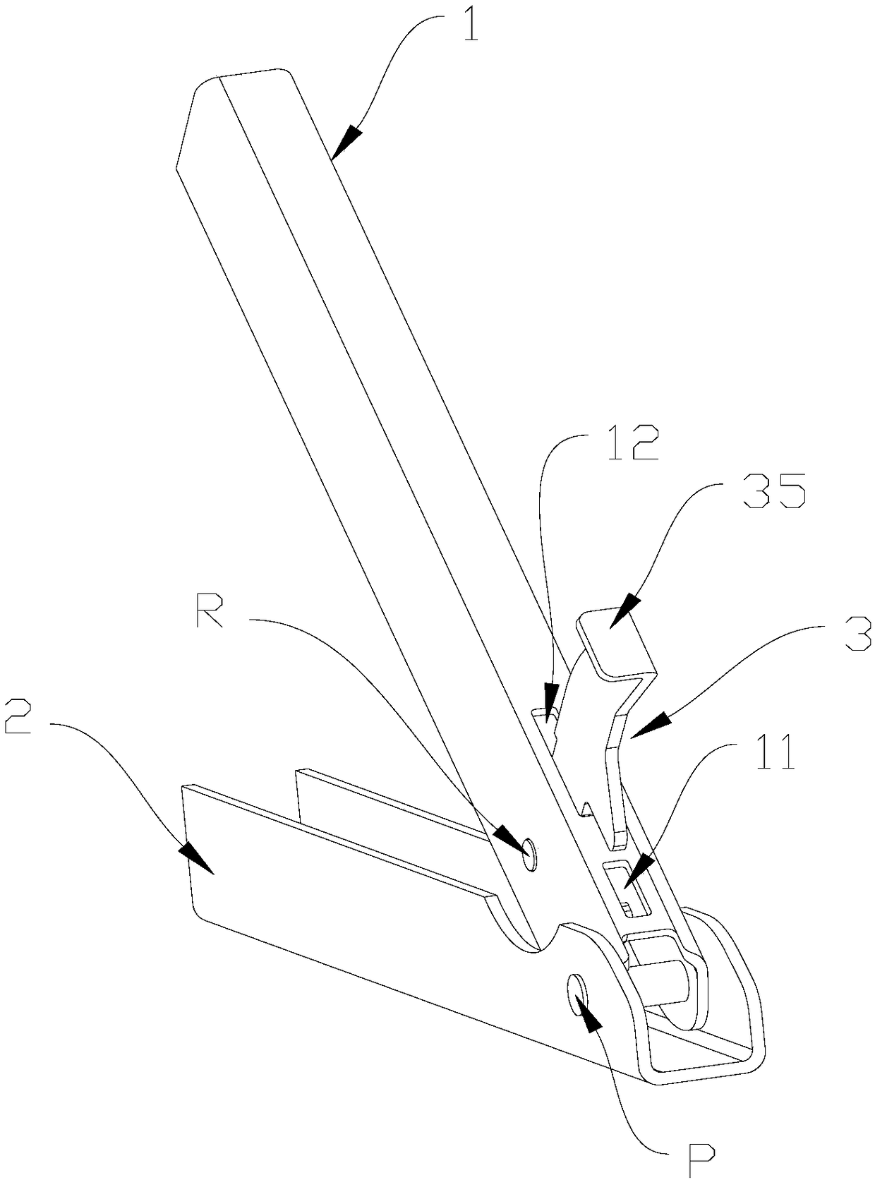
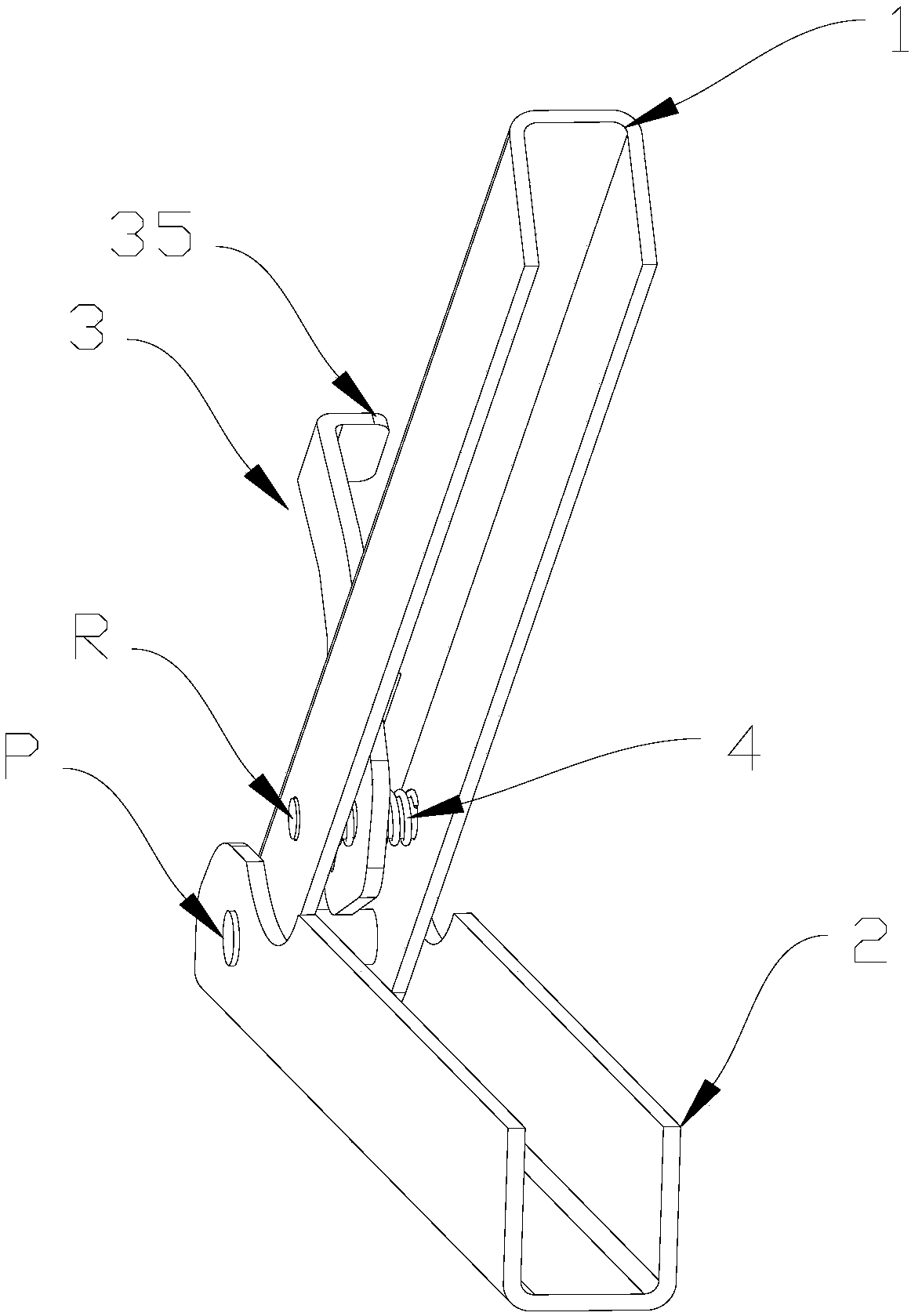
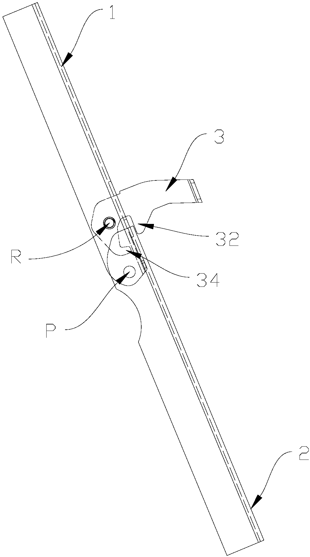
[0036] Such as Figure 1 to Figure 7 As shown, the present disclosure provides a cab strut, which includes a first strut 1 and a second strut 2 that are hinged to each other, and a locking handle 3. The locking handle 3 is hingedly connected to the first strut 1 for locking the first strut 1 and the second strut 2 on a straight line, and the locking handle 3 has an unlocking portion 34. When the unlocking direction rotates, the unlocking portion 34 can abut against the second brace 2 to make the second brace 2 rotate relative to the first brace 1.
[0037] In this disclosure, as Image 6 As shown, since the unlocking portion 34 is provided on the locking handle 3, when the locking handle 3 is rotated in the unlocking direction (counterclockwise in the figure), the unlocking portion 34 can abut against the second brace 2 to support the second brace. The rod 3 exerts a force to make the second support rod 2 rotate relative to the first support rod 1, thereby unlocking the support rod, and the unlocking operation can be completed with only one action, which is convenient and quick, and reduces the operation steps and Time improves safety.
[0038] Such as Figure 4 , Figure 5 with Figure 7 As shown, the second strut 2 is divided by the hinge point P of the first strut 1 and the second strut 2 into a first part 21 with a shorter length and a second part 22 with a longer length. In other words, the second strut 2 can be regarded as a lever, and the hinge point P of the first strut 1 and the second strut 2 serves as the fulcrum of the lever. The lever includes two moment arms located on both sides of the fulcrum, that is, the first Part 21 and second part 22. When the locking handle 3 rotates in the unlocking direction, the unlocking portion 34 can abut against the first part 21 so that the second strut 2 rotates relative to the first strut 1.
[0039] In the present disclosure, the locking handle 3 may have any suitable structure and shape. In one embodiment, such as Figure 5 with Figure 7 As shown, the locking handle 3 has a locking portion 32. The hinge point R of the locking handle 3 and the first strut 1 is arranged between the locking portion 32 and the unlocking portion 34. When the locking handle 3 is along the locking direction ( (Clockwise in the figure) when rotating, the locking portion 32 can abut against the outside of the first part 21 of the second strut 2; when the locking handle 3 rotates in the unlocking direction, the unlocking part 34 can abut against the first part 21 Inside. Specifically, when unlocking the cab brace, turn the lock handle 3 counterclockwise (unlocking direction), and the locking portion 32 is separated from the outer side of the first part 21 to unlock the cab brace; continue to turn the lock handle 3. The unlocking portion 34 presses against the inner side of the first part 21, and applies force to the first part 21, so that the second brace 2 rotates relative to the first brace 1 to complete unlocking.
[0040] In the present disclosure, a first through hole 11 through which the unlocking portion 34 can pass may be provided on the first strut 1. In this way, when the cab strut is unlocked, the unlocking portion 34 can pass through the first through hole 11 and smoothly push to the inside of the second strut 2. Specifically, such as Figure 5 with Figure 7 As shown, along the length direction of the first brace 1, the first through hole 11 is located between the hinge point P of the first brace 1 and the second brace 2 and the hinge point R of the locking handle 3 and the first brace 1 , To correspond to the position of the unlocking portion 34.
[0041] In this disclosure, as figure 1 with Figure 7 Shown. The locking handle 3 has a first arm 31 and a second arm 33. The first arm 31 and the second arm 33 respectively extend in different directions from the hinge point R of the locking handle 3 and the first strut 1, and the locking handle The handle portion 35 and the locking portion 32 of 3 are respectively formed on the first arm 31, and the unlocking portion 34 is formed on the second arm 33. The first arm 31 and the second arm 33 are formed as a lever structure with the hinge point R of the locking handle 3 and the first strut 1 as the supporting point. When unlocking, turning the handle 35 can quickly realize the support of the cab. Unlocked. Here, the length of the handle portion 35 can be appropriately increased, and the operation is more labor-saving.
[0042] In this embodiment, as Figure 5 with Figure 7 As shown, the first arm 31 can be substantially perpendicular to the second arm 33, the locking portion 32 protrudes from the first arm 31 in a direction substantially parallel to the second arm 33, and the unlocking portion 34 extends from the end of the second arm 33 It projects in a direction substantially parallel to the first arm 31. The locking portion 32 is perpendicular to the body of the first arm 31, so that it can better fit the outer side of the first strut 1 to realize the locking of the cab strut.
[0043] In the present disclosure, the first strut 1 and the second strut 2 may have any suitable structure and shape. In one embodiment, such as figure 1 with figure 2 As shown, the cross-sections of the first brace 1 and the second brace 2 are U-shaped. When the first brace 1 and the second brace 2 are in a straight line, one end of the second brace 2 is sleeved on the first brace. One end of the strut 1. On the one hand, the U-shaped structure can ensure the structural strength, and on the other hand, it is convenient to place the locking handle 3 inside it.
[0044] Specifically, such as figure 1 with figure 2 As shown, the first brace 1 includes a bottom wall and two opposite side walls. The two ends of the hinge shaft of the locking handle 3 are respectively mounted on the two side walls. The bottom wall is provided with a through hole for the locking handle 3 to pass through. The second through hole 12 and the first through hole 11 are also opened on the bottom wall. Wherein, the second through hole 12 can be set as a long hole extending along the length direction of the first strut 1 to ensure that it will not interfere with the first strut 1 when the locking handle 3 rotates. In addition, the shape of the first through hole 11 can be set as a round hole for easy processing.
[0045] In this disclosure, as figure 2 As shown, the cab strut also includes a return spring 4 for driving the locking handle 3 back to the locked position. In an embodiment, the return spring 4 may be formed as a torsion spring sleeved on the hinge shaft, one end of the torsion spring is connected to the first brace 1, and the other end is connected to the locking handle 3. In this way, after the cab is turned forward, the two support rods rotate around the hinge point P of the first support rod 1 and the second support rod 2 until they are straightened, and the locking handle 3 is rotated to the locked position under the action of the torsion spring. The locking portion 32 clamps the outer side of the second strut 2 to realize self-locking of the struts of the cab, which can hinder the tendency of the struts to bend on their own, maintain the forward turning state of the cab, and prevent the cab from falling by itself. In addition, the elastic force of the torsion spring keeps the strut in a self-locking state, and the elastic force needs to be overcome when unlocking. In this way, it is possible to avoid the situation in which the cab brace is automatically unlocked, and the safety of the cab brace operation is increased.
[0046] According to another aspect of the present disclosure, a vehicle is provided. The vehicle includes a driver's cab, a frame, and the above-mentioned driver's cab brace, and both ends of the driver's cab brace are respectively connected to the aforementioned driver's cab and the frame.
[0047] Specifically, in an embodiment of the present disclosure, the first brace 1 is an upper brace connected to the cab, and the second brace 2 is a lower brace connected to the frame. However, in other embodiments, the first brace 1 can also be a lower brace connected to the frame, and correspondingly, the second brace 2 is an upper brace connected to the cab.
[0048] The preferred embodiments of the present disclosure are described in detail above with reference to the accompanying drawings. However, the present disclosure is not limited to the specific details in the above-mentioned embodiments. Within the scope of the technical concept of the present disclosure, various simple modifications can be made to the technical solutions of the present disclosure. These simple modifications all belong to the protection scope of the present disclosure.
[0049] In addition, it should be noted that the various specific technical features described in the above-mentioned specific embodiments can be combined in any suitable manner without contradiction. In order to avoid unnecessary repetition, the present disclosure provides various possible The combination method will not be explained separately.
[0050] In addition, various different embodiments of the present disclosure can also be combined arbitrarily, as long as they do not violate the idea of ​​the present disclosure, they should also be regarded as the content disclosed in the present disclosure.

PUM

no PUM

Description & Claims & Application Information

We can also present the details of the Description, Claims and Application information to help users get a comprehensive understanding of the technical details of the patent, such as background art, summary of invention, brief description of drawings, description of embodiments, and other original content. On the other hand, users can also determine the specific scope of protection of the technology through the list of claims; as well as understand the changes in the life cycle of the technology with the presentation of the patent timeline. Login to view more.
Why Eureka
Try Eureka