Optical structure and display device

An optical structure and display device technology, applied in optics, nonlinear optics, instruments, etc., can solve problems such as poor display effect and reduced color gamut of display panels, and achieve the effects of improving contrast, increasing color gamut, and improving display effect.

Pending Publication Date: 2018-06-29
BOE TECH GRP CO LTD
View PDF6 Cites 4 Cited by
  • Summary
  • Abstract
  • Description
  • Claims
  • Application Information

AI Technical Summary

Problems solved by technology

However, in the optical structure 100 of this structure, the light emitted by the light source is emitted from both sides of the light guide plate, but the emitted light is directly emitted without the display panel 210, so the brightness has nothing to do with the display content, resulting in a dark state display ( That is, when the ambient light is dark or in a dark environment), the contrast ratio of the display screen drops sharply to about 2, which leads to a decrease in the color gamut of the display panel and poor display effect

Method used


Image

  • Optical structure and display device
  • Optical structure and display device
  • Optical structure and display device

Examples


Embodiment Construction

[0057] Specific embodiments of the present invention will be described in detail below in conjunction with the accompanying drawings. It should be understood that the specific embodiments described here are only used to illustrate and explain the present invention, and are not intended to limit the present invention.

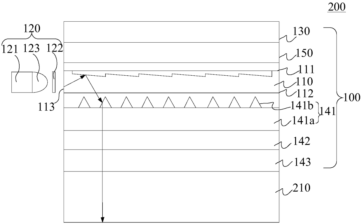
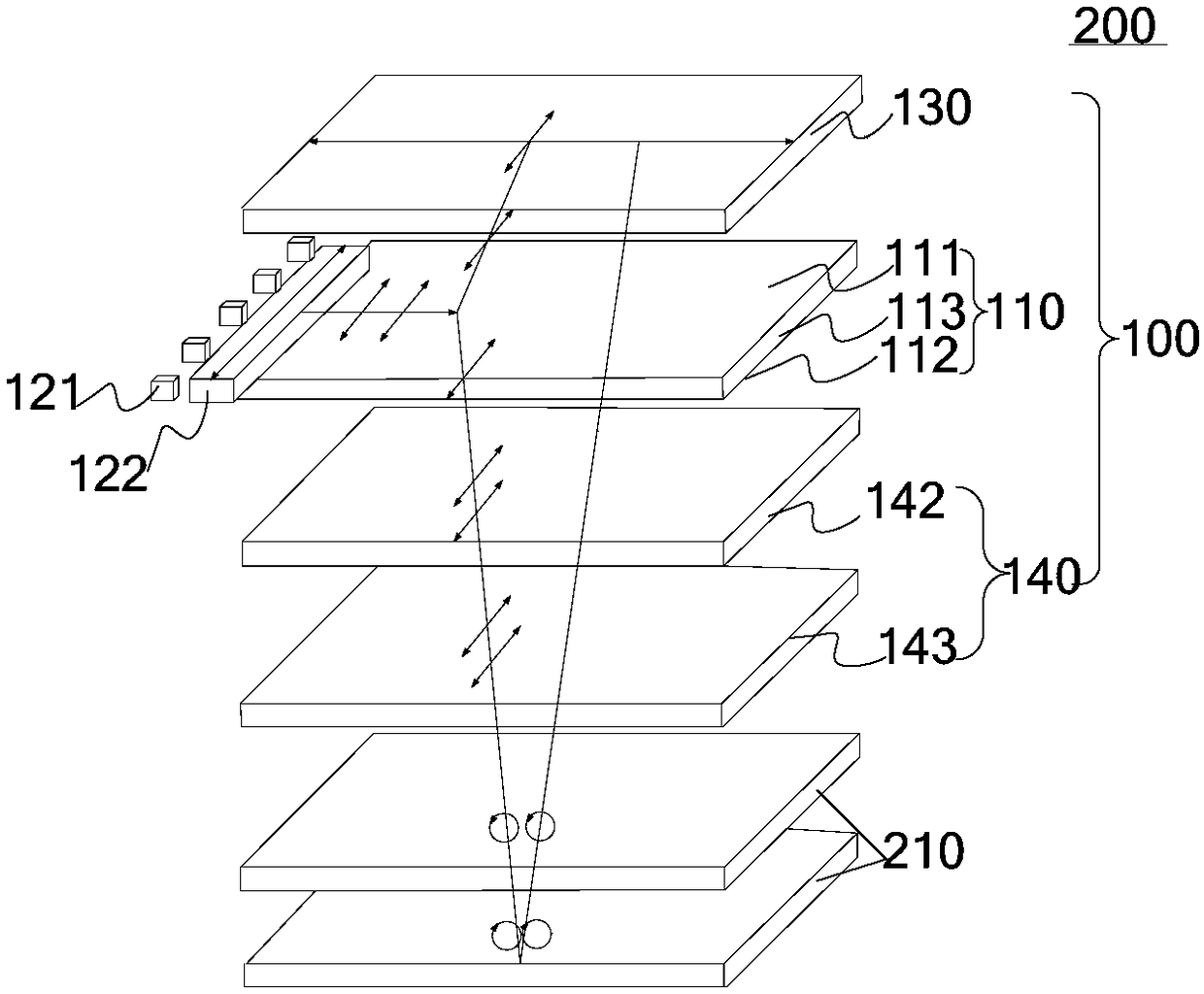
[0058] refer to figure 2 and image 3 , the first aspect of the present invention relates to an optical structure 100 suitable for a reflective display device 200 . The optical structure 100 includes a light guide plate 110, the light guide plate 110 has a first surface 111, a second surface 112, and a side 113 connecting the first surface 111 and the second surface 112, and the light guide plate 110 is on the first surface. The direction from 111 to the second surface 112 transmits light, that is, the light incident from the first surface can be emitted from the second surface 112 , and the light incident from the second surface 112 can also be emitted from ...


PUM


Abstract

The invention discloses an optical structure and a display device. The optical structure comprises a light guide plate, a power source assembly and a first polarizer. The light guide plate is providedwith a first surface, a second surface and a side surface connected with the first surface and the second surface, the first surface is arranged opposite to the second surface, and light is transmitted in the direction from the first surface to the second surface of the light guide plate; the power source assembly is arranged on the side surface and used for providing first incident light for thelight guide plate, and the first incident light is linearly polarized light in the first polarization direction; the first polarizer is arranged on the first surface, and the direction of a light transmission shaft of the first polarizer is perpendicular to the first polarization direction. When the optical structure is applied to the reflection-type display device, the display device can conductnormal display under the environment with weak environmental light. In addition, the direction of the light transmission shaft of the arranged first polarizer is perpendicular to the first polarization direction of the first incident light, and therefore the first incident light cannot be emitted from the first surface of the light guide plate; in this way, the contrast ratio of the display device can be remarkably increased, the color range of the display device is enlarged, and the display effect of the display device is improved.

Description

technical field [0001] The present invention relates to the field of display technology, in particular to an optical structure and a display device including the optical structure. Background technique [0002] Traditionally, in a reflective display device, in order to enable the display device to realize normal display even in a dark environment. Such as figure 1 As shown, the display device 200 includes a display panel 210 and an optical structure 100 arranged on the display side of the display panel 210. The optical structure 100 includes a front light source (not shown in the figure), a light guide plate with a dot structure, and a diffusion film. . However, in the optical structure 100 of this structure, the light emitted by the light source is emitted from both sides of the light guide plate, but the emitted light is directly emitted without the display panel 210, so the brightness has nothing to do with the display content, resulting in a dark state display ( That ...

Claims


Application Information

Patent Timeline
Patent Type & Authority Applications(China)
IPC IPC(8): G02F1/1335G02F1/13357
CPCG02F1/133528G02F1/1336G02F1/133615G02F1/133618
Inventor 祝明王维
Owner BOE TECH GRP CO LTD
Why Eureka
Try Eureka