Vehicle communication system
An in-vehicle communication system and communicator technology, applied in general control systems, control/regulation systems, testing/monitoring control systems, etc., can solve problems such as reduced charging efficiency and increased power consumption
- Summary
- Abstract
- Description
- Claims
- Application Information
AI Technical Summary
Problems solved by technology
Method used
Image
Examples
no. 1 approach
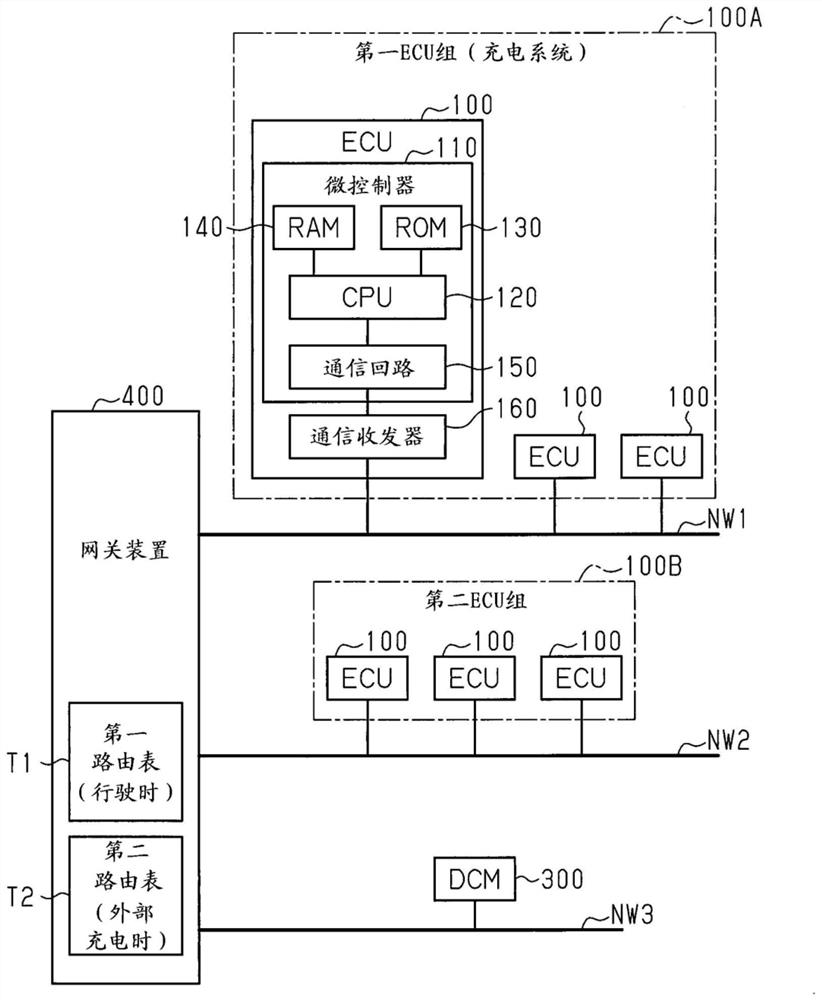
[0017] Hereinafter, a first embodiment of the in-vehicle communication system will be described with reference to the drawings.
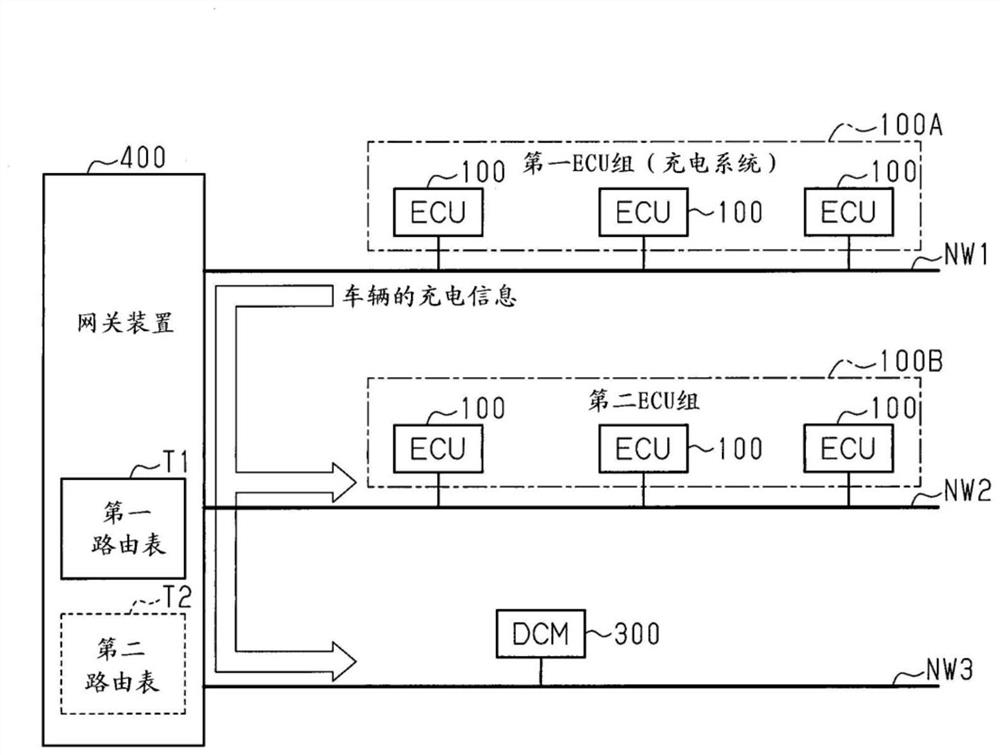
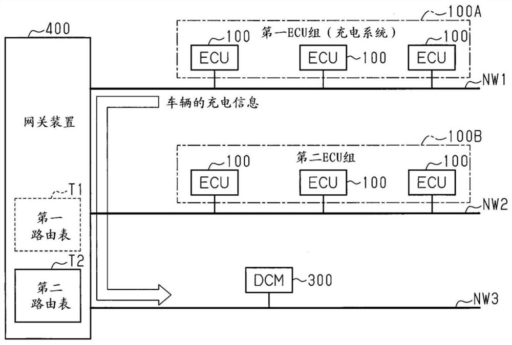
[0018] Such as figure 1 As shown, the in-vehicle communication system includes: a gateway device 400, which is installed in the vehicle and has a gateway function; a plurality of communication buses NW1-NW3 connected to the gateway device 400; ECUs (electronic control units) connected to these communication buses NW1-NW3 100 and DCM (Data Communication Module) 300 . The ECU and the DCM may be configured to include 1) one or more processors operating according to a computer program (software); 2) one or more dedicated hardware circuits such as ASIC; or 3) a circuit (circuitry) combining them. The processor includes a memory such as a CPU, RAM, and ROM, and the memory stores program codes or instructions configured to cause the CPU to execute processing. Memory or computer-readable media includes all available media that can be accessed by a general...
no. 2 approach
[0038] Next, a second embodiment of the in-vehicle communication system will be described with reference to the drawings. In addition, the second embodiment differs from the first embodiment in that, in addition to setting the routing destination of the communication message in the routing table managed by the gateway device, the routing of the communication message on the communication bus is also set. interval. The routing interval of a communication message means the time interval at which the communication message is routed. Therefore, in the following description, the configurations different from those of the first embodiment will be mainly described, and repeated descriptions of configurations that are the same as or similar to those of the first embodiment will be omitted.
[0039] Such as Figure 5 As shown, in the second embodiment, in the first routing table T1, the second communication bus NW2 and the third communication bus NW3 are set as routing destinations re...
no. 3 approach
[0046] Next, a third embodiment of the in-vehicle communication system will be described with reference to the drawings. In addition, the third embodiment is different from the first embodiment in that, in addition to setting the routing destinations of communication messages in the routing table managed by the gateway device, the routing table to be routed between communication buses is also set together. The number of data (specifically, the number of data frames). Therefore, in the following description, configurations different from those of the first embodiment will be mainly described, and redundant descriptions of configurations that are the same as or similar to those of the first embodiment will be omitted.
[0047] Such as Figure 7 As shown, in the third embodiment, in the first routing table T1, the second communication bus NW2 and the third communication bus NW3 are set as routing destinations related to the vehicle charging information from the first communicati...
PUM
 Abstract
Description
Claims
Application Information
 - R&D
- Intellectual Property
- Life Sciences
- Materials
- Tech Scout
- Unparalleled Data Quality
- Higher Quality Content
- 60% Fewer Hallucinations
Browse by: Latest US Patents, China's latest patents, Technical Efficacy Thesaurus, Application Domain, Technology Topic, Popular Technical Reports.
© 2025 PatSnap. All rights reserved.Legal|Privacy policy|Modern Slavery Act Transparency Statement|Sitemap|About US| Contact US: help@patsnap.com


