Human eye position determining method and device
A technology of the human eye and the center position, applied in the field of naked-eye 3D display, can solve the problems of increasing the difficulty of naked-eye 3D display and increasing manufacturing costs, and achieve the effect of reducing configuration, reducing difficulty, and saving production cost
- Summary
- Abstract
- Description
- Claims
- Application Information
AI Technical Summary
Problems solved by technology
Method used
Image

Examples
Embodiment 1
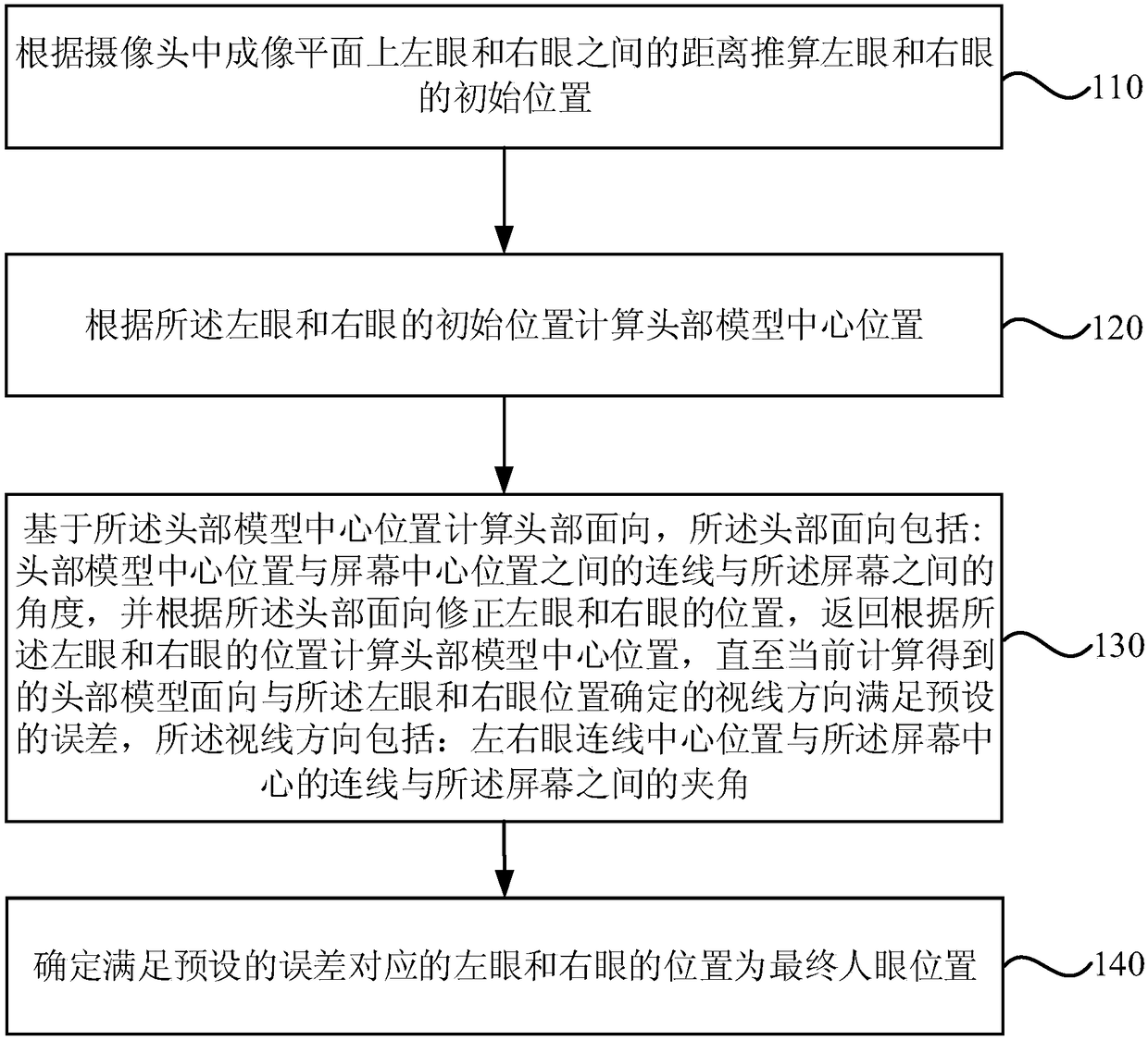
[0030] figure 1 It is a flow chart of the method for determining the position of the human eye provided in Embodiment 1 of the present invention. This embodiment is applicable to the determination of the position of the human eye. The method can be executed by a device for determining the position of the human eye. The device can use software and / or implemented in hardware. like figure 1 As shown, the method for determining the position of the human eye includes:
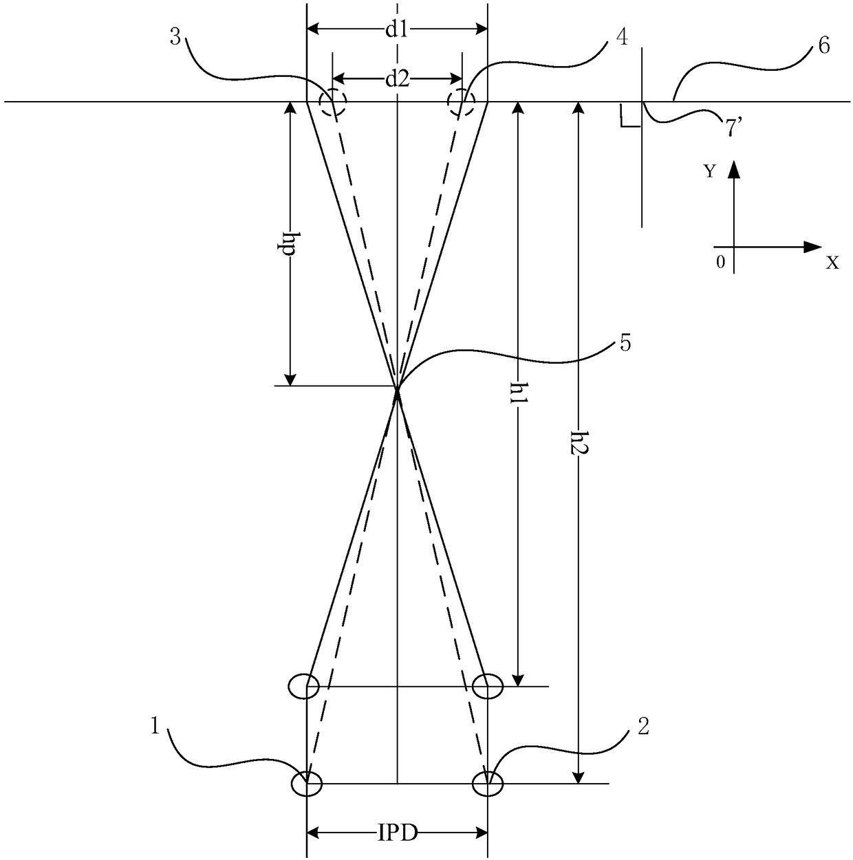
[0031] Step 110, calculate the initial positions of the left eye and the right eye according to the distance between the left eye and the right eye on the imaging plane of the camera.
[0032] In general, when calculating the position information of an object, it is usually selected to perform calculations in the coordinate system. Therefore, the embodiment of the present invention introduces a coordinate system for calculating the position of the left eye and the left eye, and subsequently calculating other posi...
Embodiment 2
[0063] Figure 10 It is a flow chart of the method for determining the position of human eyes provided by Embodiment 2 of the present invention. On the basis of Embodiment 1 above, this embodiment of the present invention further optimizes the steps of correcting the positions of the left and right eyes based on the head orientation. like Figure 10 As shown, the method for determining the position of the human eye includes:
[0064] Step 210, calculate the initial positions of the left eye and the right eye according to the distance between the left eye and the right eye on the imaging plane of the camera.
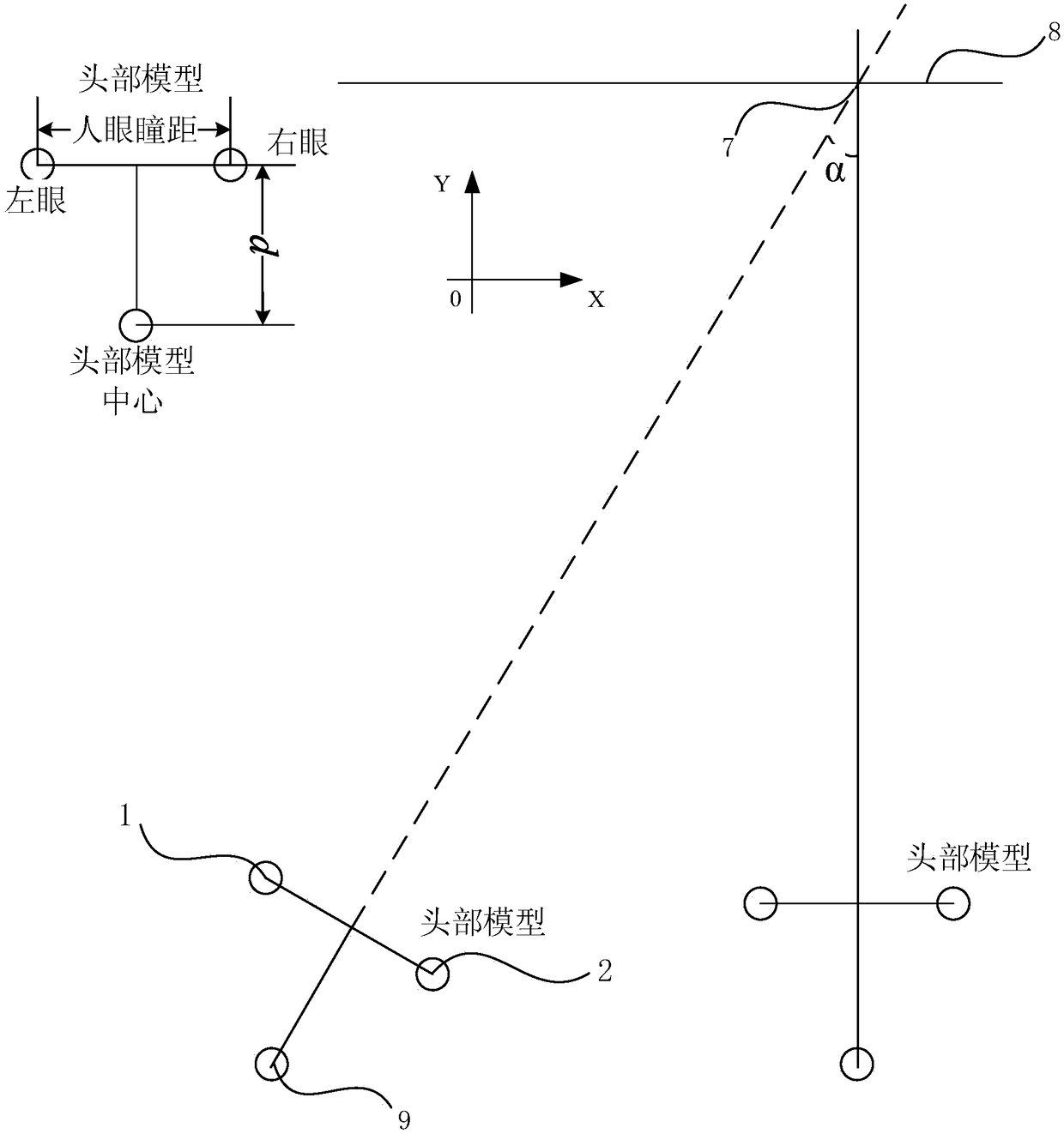
[0065] Step 220, calculate the center position of the head model according to the initial positions of the left eye and the right eye.
[0066] Step 230, calculate the head orientation based on the center position of the head model, the head orientation includes: the angle between the line between the center position of the head model and the center position of the scre...
Embodiment 3
[0093] Figure 11 It is a schematic structural diagram of the device for determining the human eye position provided in Embodiment 3 of the present invention. The device executes the method for determining the human eye position provided in any of the above embodiments, and the device can be implemented by software and / or hardware. like Figure 11 As shown, the human eye position determination device includes: left and right eye position estimation module 410, head model center calculation module 420, left and right eye position correction module 430 and left and right eye position determination module 440, wherein:
[0094] The left and right eye position estimation module 410 is configured to calculate the initial positions of the left eye and the right eye according to the distance between the left eye and the right eye on the imaging plane of the camera.
[0095] The head model center calculation module 420 is configured to calculate the center position of the head model ...
PUM
 Abstract
Description
Claims
Application Information
 - Generate Ideas
- Intellectual Property
- Life Sciences
- Materials
- Tech Scout
- Unparalleled Data Quality
- Higher Quality Content
- 60% Fewer Hallucinations
Browse by: Latest US Patents, China's latest patents, Technical Efficacy Thesaurus, Application Domain, Technology Topic, Popular Technical Reports.
© 2025 PatSnap. All rights reserved.Legal|Privacy policy|Modern Slavery Act Transparency Statement|Sitemap|About US| Contact US: help@patsnap.com