Efficient sealing machine

A stamping machine and high-efficiency technology, applied in the field of stamping, can solve the problems of waste of human resources, inaccurate manual operation, unclear position of stamps, etc., and achieve the effect of automatic control switching, simple structure and convenient operation.

Inactive Publication Date: 2018-07-03
广州航爵数码科技有限公司
View PDF3 Cites 0 Cited by
  • Summary
  • Abstract
  • Description
  • Claims
  • Application Information

AI Technical Summary

Problems solved by technology

[0002] A large number of architectural drawings, tax bills, etc. need to be stamped. At present, manual stamping is used. The staff repeats simple labor, which seriously wastes human resources and is inefficient. And because the manual operation is not accurate enough, the stamped seals are not perfect. For the problem of clarity or position offset, the existing stamping machines on the market can only stamp one stamp at a time, and it is very troublesome to manually replace different stamps according to the actual situation, which cannot meet the existing needs

Method used


Image

  • Efficient sealing machine
  • Efficient sealing machine
  • Efficient sealing machine

Examples


Embodiment Construction

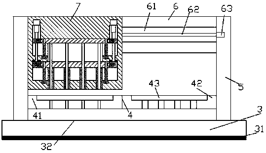
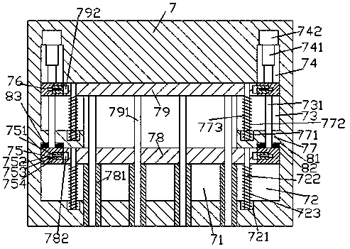
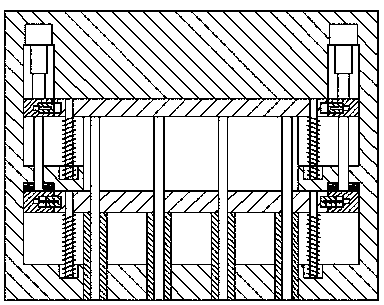
[0025] like Figure 1-Figure 8 As shown, a high-efficiency stamping machine of the present invention includes a frame body and a stamping device 7, and the stamping device 7 is provided with an accommodating cavity 71, and the left and right sides of the accommodating cavity 71 correspond from top to bottom A first sliding groove 73, a partition plate 77 and a second sliding groove 72 are provided, and a first sliding rod 79 extending left and right is arranged above the accommodating chamber 71, and the tip of the first sliding rod 79 extends left and right. Respectively extending into the first sliding grooves 73 on the left and right sides and slidingly fitted and connected, a second sliding rod 78 extending left and right is provided below the receiving chamber 71, and the left and right sides of the second sliding rod 78 Stretching ends extend into the second sliding grooves 72 on the left and right sides respectively and are connected by sliding fit. A seal 781, each of...


PUM


Abstract

The invention discloses an efficient sealing machine which comprises a support and a sealing device. The sealing device is internally provided with a containing cavity, a first sliding movement groove, a partition panel and a second sliding movement groove are correspondingly arranged on each of the left and right sides of the containing cavity from top to bottom, a first sliding movement rod arranged in a left-and-right stretching manner is arranged above the containing cavity, left and right extending tips of the first sliding movement rod extend to the interiors of the first sliding movement grooves on the left and right sides and are connected with the first sliding movement grooves in a sliding fit manner, a second sliding movement rod arranged in a left-and-right extending manner isarranged below the containing cavity, left and right extending tips of the second sliding movement rod extend into the second sliding movement grooves on the left and right sides and are connected with the second sliding movement grooves in a sliding fit manner, the bottoms of the second sliding movement rods are provided with first seals arranged in a downwards-extending manner and penetrating the bottom of the seal device, and a second seal arranged in an up-and-down extending manner is connected into each first seal in a sliding fit manner. The efficient sealing machine is simple in structure, reasonable in design, convenient to operate, capable of achieving automatic control over switching of the two kinds of seals, capable of improving the working efficiency, and low in manufacturingcost and maintaining cost.

Description

technical field [0001] The invention relates to the technical field of stamping, in particular to a high-efficiency stamping machine. Background technique [0002] A large number of architectural drawings, tax bills, etc. need to be stamped. At present, manual stamping is used. The staff repeats simple labor, which seriously wastes human resources and is inefficient. And because the manual operation is not accurate enough, the stamped seals are not perfect. For the problem of clarity or position offset, the existing stamping machines on the market can only stamp one stamp at a time, and it is very troublesome to manually replace different stamps according to the actual situation, which cannot meet the existing needs. Contents of the invention [0003] The technical problem to be solved by the present invention is to provide a high-efficiency stamping machine, which can solve the above-mentioned problems in the prior art. [0004] The present invention is achieved through ...

Claims


Application Information

Patent Timeline
Patent Type & Authority Applications(China)
IPC IPC(8): B41K3/04B41K3/62
CPCB41K3/04B41K3/62
Inventor 汪女
Owner 广州航爵数码科技有限公司
Why Eureka
Try Eureka