
Brake master cylinder of brake system and brake system with same

A technology of brake master cylinder and brake system, applied in the direction of brake transmission, hydraulic brake transmission, brake, etc. The problem of limited acting force, etc., can achieve the effect of taking into account the braking pressure, taking into account the braking stroke and good braking performance

Active Publication Date: 2019-11-22
BYD CO LTD
View PDF6 Cites 0 Cited by
  • Summary
  • Abstract
  • Description
  • Claims
  • Application Information

AI Technical Summary

Problems solved by technology

If you want to ensure the brake pressure generated by the brake master cylinder and the displacement of the brake fluid at the same time, you need to increase the piston stroke or the force of the person on the pedal. However, if the piston stroke is too large, the distance for people to pedal Large, and the force of the person on the pedal is limited, increasing the piston stroke or the force of the person on the pedal will reduce the comfort of the user's operation
The brake master cylinder in the prior art cannot balance pedal force and pedal travel

Method used


Image

  • Brake master cylinder of brake system and brake system with same
  • Brake master cylinder of brake system and brake system with same
  • Brake master cylinder of brake system and brake system with same

Examples


Embodiment Construction

[0045] Embodiments of the present invention are described in detail below, examples of which are shown in the drawings, wherein the same or similar reference numerals designate the same or similar elements or elements having the same or similar functions throughout. The embodiments described below by referring to the figures are exemplary only for explaining the present invention and should not be construed as limiting the present invention.

[0046]In describing the present invention, it should be understood that the terms "center", "longitudinal", "transverse", "length", "width", "thickness", "upper", "lower", "front", " The orientation or positional relationship indicated by "rear", "left", "right", "inner", "outer", etc. is based on the orientation or positional relationship shown in the drawings, and is only for the convenience of describing the present invention and simplifying the description, rather than Nothing indicating or implying that a referenced device or elemen...


PUM


Abstract

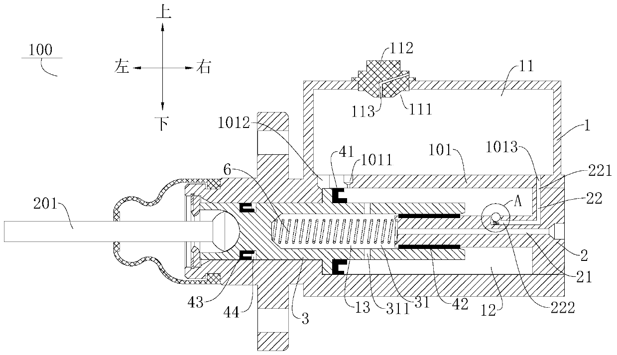
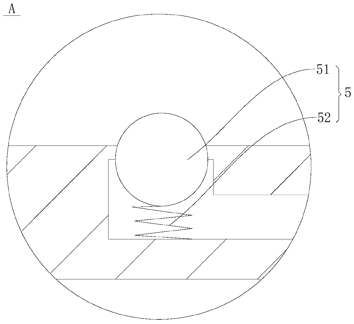
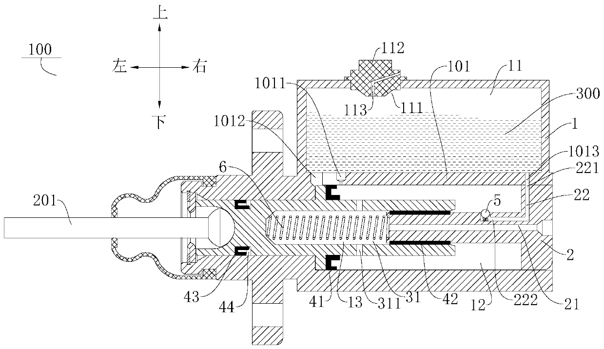
The invention discloses a braking main cylinder and a braking system. The braking main cylinder comprises a cylinder body, a communicating piece and a piston, wherein a liquid storage cavity and a first hydraulic cavity are limited in the cylinder body; the communicating piece is arranged in the first hydraulic cavity; and the piston is internally provided with a groove, and the groove is formed in the exterior of the communicating piece in a sleeving mode. A second hydraulic cavity is limited jointly by the communicating piece and the groove, and communicates with a communicating channel mutually. The piston is provided with a stopping position, a first braking position and a second braking position in the from-left-to-right moving process, when the piston is located at the stopping position, the liquid storage cavity, the first hydraulic cavity and the second hydraulic cavity communicate with one another; when the piston moves to the first braking position, the liquid storage cavityand the first hydraulic cavity are cut off, and the first hydraulic cavity and the second hydraulic cavity communicate with each other; and when the piston moves to the second braking position, the liquid storage cavity communicates with the first hydraulic cavity, and the first hydraulic cavity and the second hydraulic cavity are cut off. According to the braking main cylinder, the braking performance is good, and the braking stroke and braking pressure can be taken into account simultaneously.

Description

technical field [0001] The invention relates to the technical field of brake systems, in particular to a brake master cylinder of the brake system and a brake system with the brake master cylinder. Background technique [0002] The brake master cylinder is mainly used in the brake system, and the brake fluid is pushed into the brake by manpower pushing the push rod to realize the brake. In related technologies, the brake master cylinder is mostly a single-piston brake master cylinder, and its braking performance mainly depends on the bore and stroke of the brake master cylinder. The bore determines the brake pressure, and the stroke determines the displacement of the brake fluid. [0003] In the case of the same stroke, the larger the piston area of ​​the brake master cylinder, the larger the brake fluid displacement, and the smaller the brake pressure generated; the smaller the piston area, the smaller the displacement, and the larger the brake pressure generated. In addit...

Claims


Application Information

Patent Timeline
Patent Type & Authority Patents(China)
IPC IPC(8): B60T11/16B60T11/236B60T11/18
CPCB60T11/16B60T11/18B60T11/236
Inventor 何锡阳
Owner BYD CO LTD
Learn More