Variable sweepback wing based on bionics

A technology of sweep angle and wing, which is applied in the direction of wing, wing adjustment, wing shape, etc., can solve the problems of small deformation range of sweep angle, interference of wing ribs, complex mechanism, etc., and achieve simple mechanism deformation , Simple driving method, simple control effect

Inactive Publication Date: 2018-07-03
HARBIN INST OF TECH
View PDF6 Cites 6 Cited by
  • Summary
  • Abstract
  • Description
  • Claims
  • Application Information

AI Technical Summary

Problems solved by technology

[0004] In order to solve the problem that the existing variable-sweep angle wing mechanism is complicated, the deformation range of the sweep angle is small, and the wing structure mainly composed of trusses will produce wing-rib interference when large deformation occurs, the present invention further proposes a A bionic-based variable-sweep wing

Method used


Image

  • Variable sweepback wing based on bionics
  • Variable sweepback wing based on bionics
  • Variable sweepback wing based on bionics

Examples


specific Embodiment approach 1

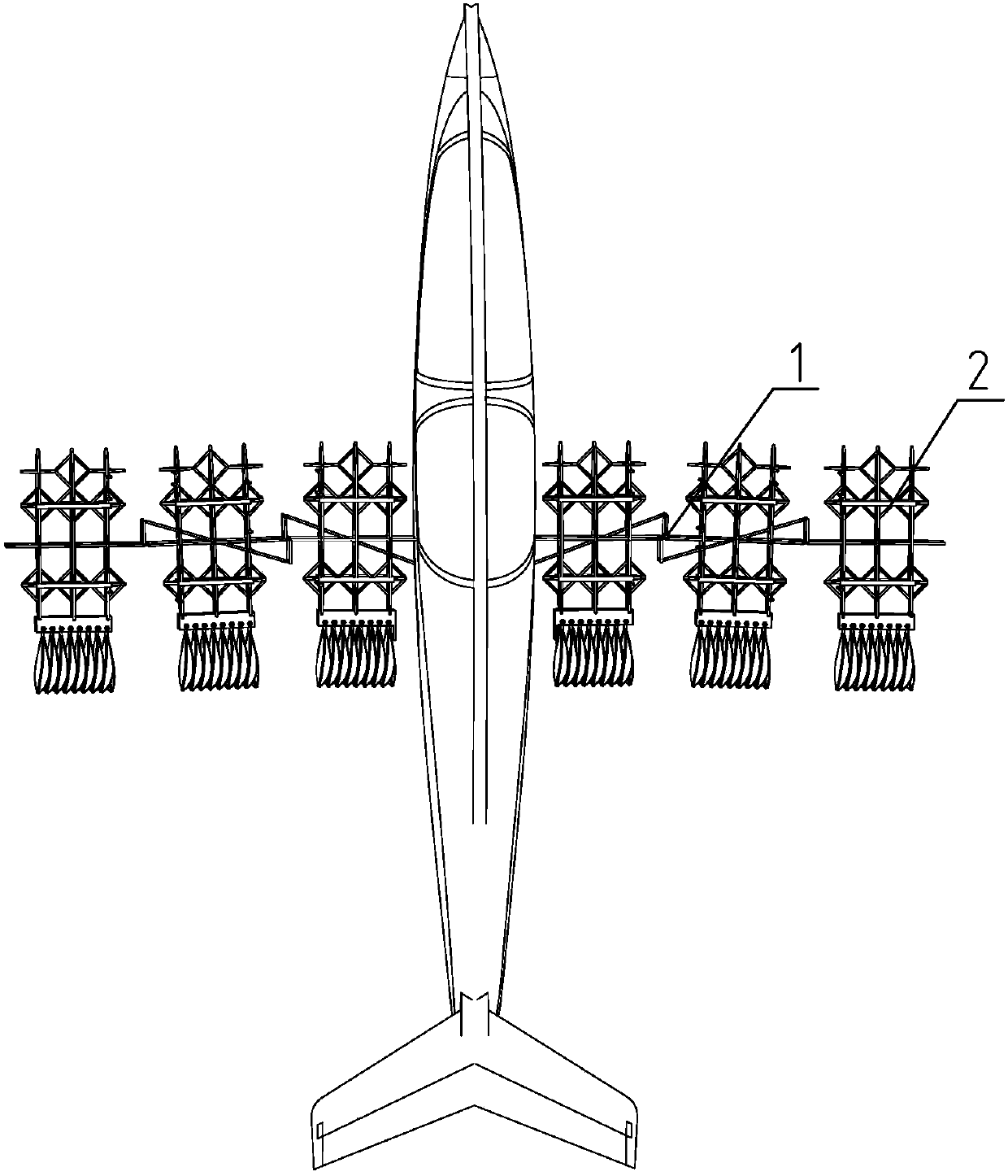
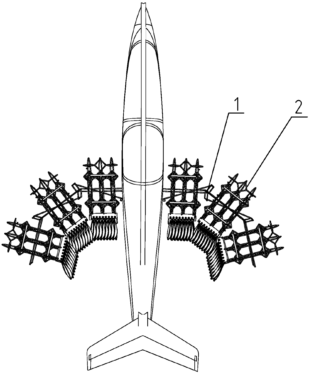
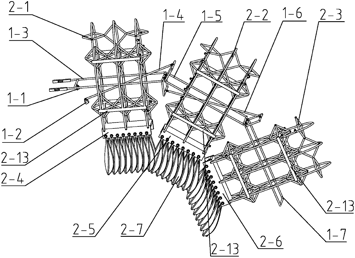
[0021] Specific implementation mode one: combine Figure 1 to Figure 8 Describe this embodiment. A bionic-based variable-sweep-angle wing described in this embodiment includes a skeleton deformation mechanism 1 and an anti-interference feather load-bearing mechanism 2. The skeleton deformation mechanism 1 includes a beam fixed end 1-1, a connecting rod Fixed end 1-2, humerus-like beam 1-3, humerus-like connecting rod 1-4, ulnar-like flexural bone beam 1-5, ulnar-like flexural bone connecting rod 1-6, metacarpal bone-like beam 1-7, humerus-like beam 1-3, ulnar-like flexural beams 1-5 and metacarpal bone-like beams 1-7 are arranged in sequence along the lengthwise direction, the shape of humerus-like beams 1-3, ulnar-like flexural beams 1-5 and metacarpal bone-like beams 1-7 All are L-shaped, the long end of the humerus-like beam 1-3 is rotationally connected with the fixed end 1-1 of the beam, the turning point of the humerus-like beam 1-3 is rotationally connected with the tur...

specific Embodiment approach 2

[0033] Specific implementation mode two: combination Figure 1 to Figure 5 Describe this embodiment, this embodiment feather 2-7 is arranged obliquely, and the edge of the blade of the previous feather 2-7 is in contact with the middle protrusion of the blade of the next feather 2-7. Other compositions and connection methods are the same as those in Embodiment 1.

specific Embodiment approach 3

[0034] Specific implementation mode three: combination Figure 4 To illustrate this embodiment, the end of the humerus-like C-beam 2-4 in this embodiment near the fuselage end is fixedly connected with a baffle plate 2-12. Other compositions and connection methods are the same as those in the second embodiment.

[0035] This design acts as a limiter for the innermost feather 2-7. In the second change process, due to the existence of the baffle plate 2-12 near the fuselage side of the anti-interference feather mechanism on the humerus C-shaped beam 2-4 , the side edge of the anti-interference feather mechanism near the fuselage side feather 2-7 on the humerus C-shaped beam 2-4 will lean against the baffle plate 2-12, and the position is fixed.


PUM


Abstract

The invention discloses a variable sweepback wing based on bionics, and relates to the technical field of deformable aircrafts. The variable sweepback wing solves the problems that an existing variable sweepback wing is complex in mechanism and small in sweepback deformation range, and wing rib interference occurs when a wing structure taking a truss as the main part is subjected to large deformation. The variable sweepback wing comprises a skeleton deformation mechanism and an anti-interference feather force-bearing mechanism, the skeleton deformation mechanism comprises a beam fixing end, aconnecting rod fixing end, a humerus-like beam, a humerus-like connecting rod, a radius-like beam, a radius-like connecting rod and a metacarpal-bone-like beam, and the anti-interference feather forcebearing mechanism comprises a truss mechanism and three sets of anti-interference feather mechanisms; and the truss mechanism comprises a humerus-like truss, a radius-like truss, a metacarpal-bone-like truss, a humerus-like C-shaped beam, a radius-like C-shaped beam and a metacarpal-bone-like C-shaped beam, and the opening ends of the humerus-like C-shaped beam, the radius-like C-shaped beam andthe metacarpal-bone-like C-shaped beam are each provided with one set of anti-interference feather mechanisms. The variable sweepback wing based on bionics can be used for the deformable aircrafts.

Description

technical field [0001] The invention relates to the technical field of deformable aircraft, in particular to a bionic-based variable-sweep-angle wing. Background technique [0002] Straight-wing aircraft are prone to disintegration due to excessive shock wave resistance during high-speed dives. Although fixed-sweep wing aircraft can reduce wave resistance, increase flight speed, and shorten take-off and landing distances, they have insufficient leading edge lift and take-off , Landing, and various indicators of airspeed restrictions cannot achieve the desired results. Therefore, there is an urgent need for a variable-sweep wing with a simple structure and flexible deformation in the field of deformable aircraft design. On the other hand, the existing variable-sweep angle wing designs mostly use complex structures and multiple driving sources to realize the deformation of the wing, resulting in an overly complex aircraft structure, a small range of sweep angle changes, and a...

Claims


Application Information

Patent Timeline
Patent Type & Authority Applications(China)
IPC IPC(8): B64C3/40B64C3/10B64C3/18
CPCB64C3/10B64C3/182B64C3/40
Inventor 李柠汐张荣茹张征徐晓涵张继元
Owner HARBIN INST OF TECH
Why Eureka
Try Eureka