Transformer paper tube bonding device

A technology for bonding devices and transformers, which is applied in the manufacture of inductors/transformers/magnets, cardboard-wrapped articles, and coil manufacturing. , the effect of uniform force

Pending Publication Date: 2018-07-03
JIANGSU HUACHEN TRANSFORMER
View PDF0 Cites 0 Cited by
  • Summary
  • Abstract
  • Description
  • Claims
  • Application Information

AI Technical Summary

Problems solved by technology

[0002] The transformer paper tube is an important part of the transformer winding, and its wall thickness is usually 4 to 6mm. At present, the production of the transformer paper tube is generally made of 0.1mm thin insulating cardboard to wrap the movable winding, which is not only time-consuming and labor-intensive, but also inefficient. , and the bonding between the layers of the transformer paper tube is not strong, and air bubbles are prone to appear, which seriously affects the quality of the transformer paper tube
There is also a method of manufacturing transformer paper tubes, which is to directly roll cardboard with a thickness of 4 to 6 mm into a cardboard tube with seams, and then use adhesive to bond the seams. However, due to the thick cardboard, it is difficult to It is necessary to bundle the paper tubes in advance, and apply a certain pressure on the overlapped and bonded parts of the cardboard tubes along the busbar to ensure the bonding quality. When pressing, screw or hydraulic pressure is used for pressing, which is not convenient for the formed transformer. The removal of the paper tube is usually completed with the help of other equipment, which is laborious and laborious, and the efficiency is low

Method used


Image

  • Transformer paper tube bonding device
  • Transformer paper tube bonding device
  • Transformer paper tube bonding device

Examples


Embodiment Construction

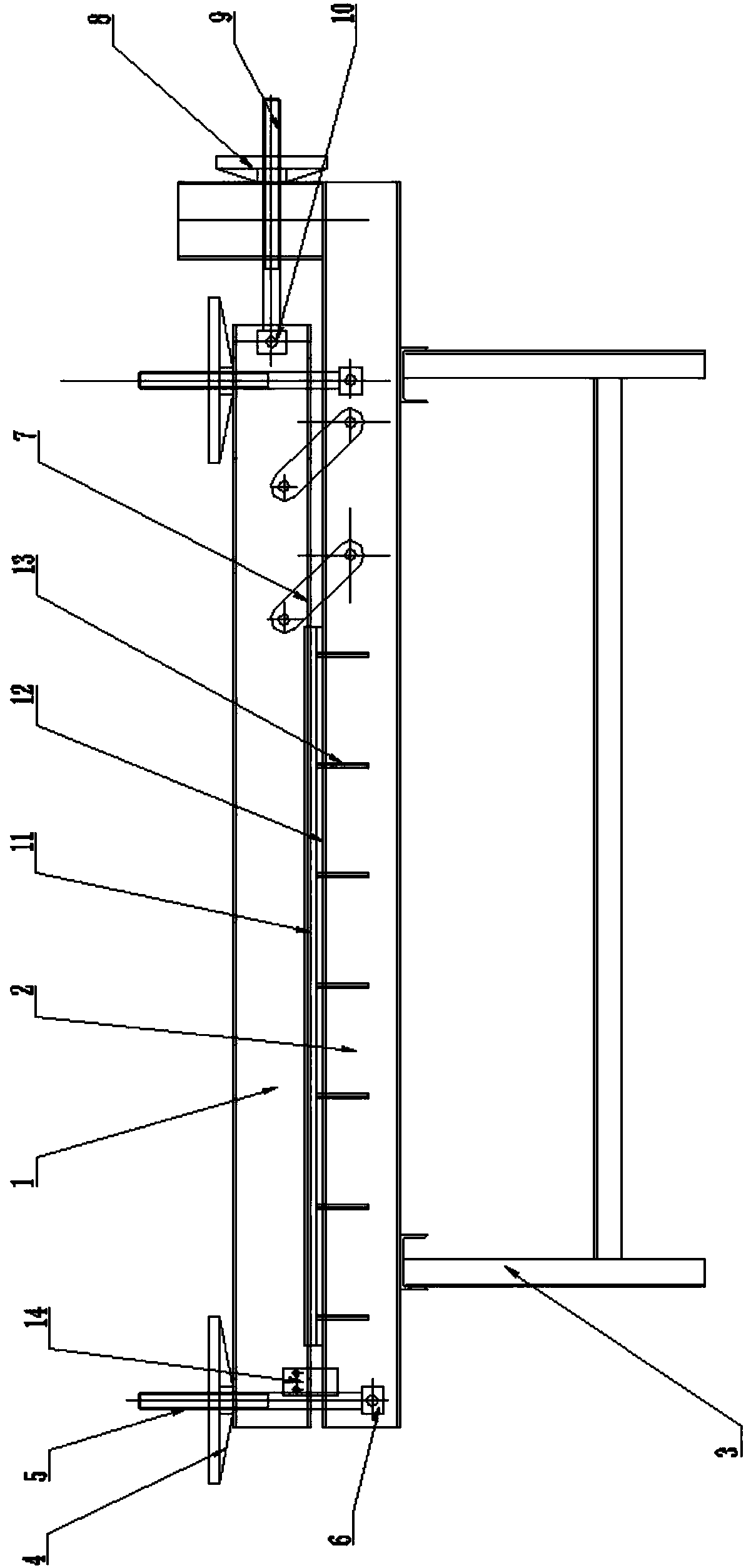
[0025] The present invention will be further described below in conjunction with accompanying drawing. For convenience of description, define figure 1 The left side is left, the right side is right, the upper end is upper, and the lower end is lower.

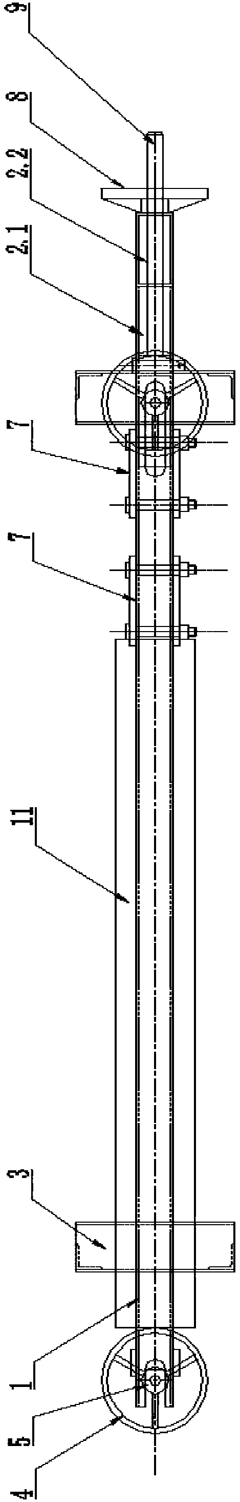
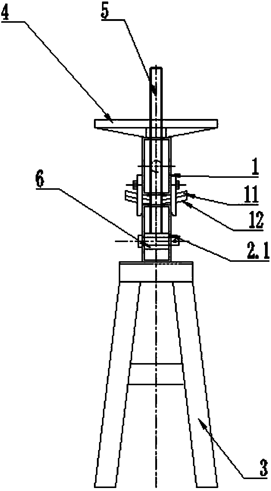
[0026] Such as Figures 1 to 12 As shown, a transformer paper tube bonding device includes an upper platen 1, a base 3 below the lower support plate 2, a punch 11 is fixed on the lower end of the upper platen 1, a die 12 is fixed on the upper end of the lower support base 2, and the lower support The plate 2 is fixed on the lower base 3, the upper platen 1 is a rectangular frame, the lower support plate 2 includes a beam 2.1 and a vertical support seat 2.2, the beam 2.1 and the vertical support seat 2.2 are both rectangular frames, and the vertical support seat 2.2 is fixed on the beam 2.1 On the upper end of one side, the length of the upper platen 1 is less than the length of the crossbeam 2.1, and the left and right ends of...


PUM


Abstract

The invention discloses a transformer paper tube bonding device. An upper press plate is a rectangular frame; a lower support plate comprises a cross beam and a vertical support seat; the cross beam and the vertical support seat are both a rectangular frame; the vertical support seat is fixed at the upper end on one side of the cross beam; the length of the upper press plate is less than the length of the cross beam; a compaction device is arranged at the left and right ends of the upper press plate respectively; a screw I is fixed at the upper end of a fixing block I and sequentially passes through an oblong hole in the cross beam and an oblong hole in the upper press plate; a hand wheel I is mounted at a threaded end on the upper side of the screw I; a connecting rod is articulated between the upper press plate and the cross beam; when the left end surface of the upper press plate is level with the left end surface of the cross beam, the center line of the articulation hole in the upper press plate does not stay on the same vertical line with the center line of the articulation hole in the cross beam; and a stretching device is arranged on the vertical support seat. In the invention, the structure is simple, the transformer paper tube bonding side is under uniform stress, the finished product can be taken out easily without auxiliary equipment, and thus the device has high efficiency and is convenient to use.

Description

technical field [0001] The invention relates to a transformer paper cylinder bonding device, which belongs to the technical field of manufacturing equipment for transformer insulating parts. Background technique [0002] The transformer paper tube is an important part of the transformer winding, and its wall thickness is usually 4 to 6mm. At present, the production of the transformer paper tube is generally made of 0.1mm thin insulating cardboard to wrap the movable winding, which is not only time-consuming and labor-intensive, but also inefficient. , and the bonding between the layers of the transformer paper tube is not strong, and air bubbles are prone to appear, which seriously affects the quality of the transformer paper tube. There is also a method of manufacturing transformer paper tubes, which is to directly roll cardboard with a thickness of 4 to 6 mm into a cardboard tube with seams, and then use adhesives to bond the seams. However, due to the thick cardboard, whe...

Claims


Application Information

Patent Timeline
Patent Type & Authority Applications(China)
IPC IPC(8): H01F41/12B31C1/08
CPCH01F41/125B31C1/08
Inventor 张永华张孝金
Owner JIANGSU HUACHEN TRANSFORMER
Why Eureka
Try Eureka