A combined flower pot

A combination and flowerpot technology, which is applied in gardening, gardening methods, botanical equipment and methods, etc., can solve the problems of uniform illumination of flowers, inability to loosen soil and ventilation, and inability to perform good display, etc., to achieve light Uniformity, avoiding the effect of growth skew

Active Publication Date: 2019-11-26
潘熹
View PDF6 Cites 0 Cited by
  • Summary
  • Abstract
  • Description
  • Claims
  • Application Information

AI Technical Summary

Problems solved by technology

But this invention can't carry out good display, can't make flower illumination evenly, can't carry out soil loosening and ventilation

Method used


Image

  • A combined flower pot
  • A combined flower pot
  • A combined flower pot

Examples


specific Embodiment approach 1

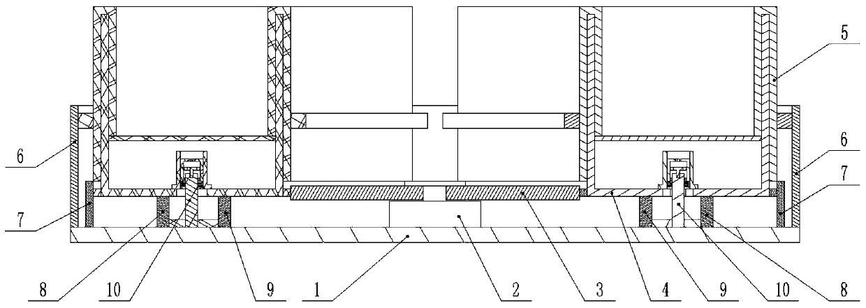
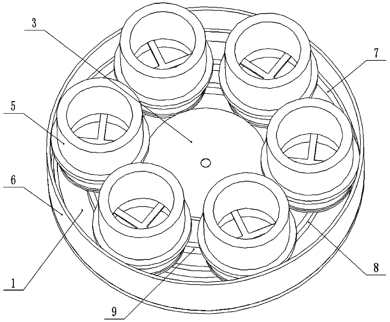
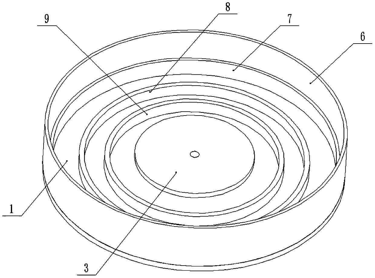
[0034] Combine below Figure 1-14Describe this embodiment, a combined flower pot, including a circular bottom plate 1, a drive motor 2, a drive gear 3, a flower pot lining body 4, a flower pot cover 5, an inner gear I6, an inner gear II7, an inner gear Ring III8, outer gear I9 and half-tooth ventilation assembly 10, the drive motor 2, inner gear I6, inner gear II7, inner gear III8 and outer gear I9 are all fixedly connected to the circular bottom plate 1, the The drive motor 2, the external gear I9, the internal gear III8, the internal gear II7 and the internal gear I6 are distributed sequentially from the inside to the outside and are coaxial, and the drive gear 3 is fixedly connected to the drive shaft of the drive motor 2, so The drive gear 3 is meshed with a plurality of flowerpot inner linings 4 through gear meshing, and the plurality of flowerpot inner linings 4 are evenly distributed in a circular shape. Mesh connection, the flower pot liner 4 is rotatably connected to...

specific Embodiment approach 2

[0036] Combine below Figure 1-14 This embodiment will be described. This embodiment will further describe Embodiment 1. The flowerpot lining body 4 includes a flowerpot barrel body 4-1 and an external gear II 4-2, and the external gear II 4-2 is fixedly connected to the The outer end of the flowerpot barrel body 4-1, the lower end surface of the flowerpot barrel body 4-1 is attached to the upper end surface of the inner ring gear III8 and the outer ring gear I9, and the driving gear 3 and the inner ring gear II7 are both It meshes with the outer ring gear Ⅱ4-2; the inner ring gear Ⅱ7 is fixed, and while the drive gear 3 drives the outer ring gear Ⅱ4-2 to rotate itself, the outer ring gear Ⅱ4-2 revolves along the inner ring gear Ⅱ7, which not only affects the inner lining of the flowerpot 4. The flowers in the interior are displayed in revolution, and the orientation of the flowers will be rotated and transformed to prevent the flowers from being fixed, which will cause the fl...

specific Embodiment approach 3

[0038] Combine below Figure 1-14 Describe this embodiment, this embodiment will further explain Embodiment 2, the bottom end of the inside of the flowerpot barrel 4-1 is fixedly connected with a plunger sleeve 4-3, and the bottom of the flowerpot barrel 4-1 The lower end is provided with a threaded through hole 4-4, and the lower end of the flower pot barrel 4-1 is provided with a plurality of fan-shaped vents 4-5, and the plurality of fan-shaped vents 4-5 communicate with the threaded through hole 4-4; The toothed ventilation assembly 10 is connected in the threaded through hole 4-4 through thread fit, and during the reciprocating movement of the half-toothed ventilation assembly 10 up and down, a plurality of fan-shaped ventilation openings 4-5 play a ventilation role.


PUM


Abstract

The invention relates to a flowerpot, in particular to a combined flowerpot which comprises a round baseplate, a driving motor, a driving gear, multiple flowerpot lining bodies, multiple flowerpot sleeves, an inner tooth ring I, an inner tooth ring II, an inner tooth ring III, an outer tooth ring I and a half-tooth ventilation component, the driving gear is fixedly connected on a transmission shaft of the driving motor and is in meshed connection with the flowerpot lining bodies through gears, the outer ends of the flowerpot lining bodies are in meshed connection with the inner tooth ring II through gears, the flowerpot lining bodies are rotatably connected inside the flower sleeves which are in meshed connection with the inner tooth ring I through gears, the lower ends of the flowerpot lining bodies are in matched connection with the half-tooth ventilation component through threads, and the lower end of the half-tooth ventilation component is in meshed connection with the inner toothring III or the outer tooth ring I through gears. The combined flowerpot can realize autorotation of flowers and plants to ensure uniform illumination and can realize soil loosening of roots of the flowers and the plants and forced ventilation of the inside of each flowerpot lining body.

Description

technical field [0001] The invention relates to a flowerpot, more specifically to a combined flowerpot. Background technique [0002] For example, the patent application number is CN201410769272.8, a combined multifunctional flower pot, the loam cake (1) is fixedly installed on the outer barrel (7), and the middle of the loam cake is provided with a reserved hole (13), and the outer edge of the loam cake and the preset The reserved holes (13) are all geometric shapes, the inner barrel (3) is arranged in the reserved hole, the inner barrel is placed on the boss (73) at the bottom of the outer barrel, and the bottom of the inner barrel is provided with water-absorbing parts and ventilation holes (33). (4) Covered on the water injection port (12), the flower tray (8) is placed on the flower tray placement table (34) on the side wall of the inner barrel, the water drawing part (A) is arranged on the flower tray, and the seal (C) is sealed Hold the absorbent part and vent (33). ...

Claims


Application Information

Patent Timeline
Patent Type & Authority Patents(China)
IPC IPC(8): A01G9/02A01G7/06
CPCA01G7/06A01G9/02
Inventor 黄明才
Owner 潘熹
Why Eureka
Try Eureka