
Iron plate twisting device

An iron plate and twisting technology, which is applied in the field of iron plate twisting devices, can solve the problems of insufficient fixing, waste of manpower, and unbeautiful product shape.

Inactive Publication Date: 2018-07-06
江苏悍威汽车有限公司
View PDF0 Cites 3 Cited by
  • Summary
  • Abstract
  • Description
  • Claims
  • Application Information

AI Technical Summary

Problems solved by technology

[0002] The existing manual twisting and bending device for thin iron plates is not fixed tightly enough, resulting in unattractive product shapes during processing, and it will waste manpower because the iron plates are loose during processing

Method used


Image

  • Iron plate twisting device

Examples


Embodiment

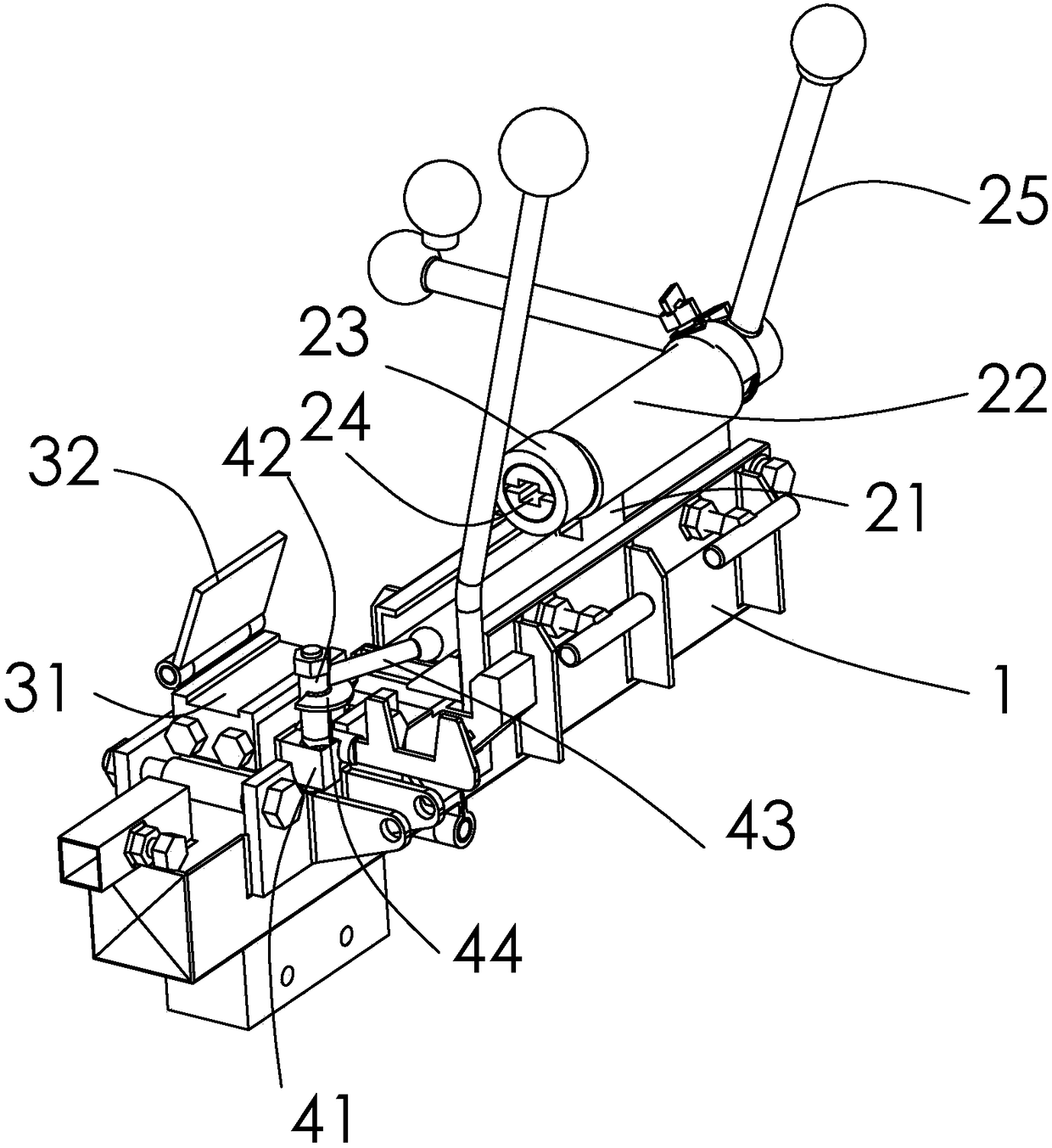
[0019] figure 1 As shown, an iron plate twisting device includes a platform 1 and a clamping and twisting device and a first clamping device provided on the platform 1;

[0020] The twisting device includes a support base 21 arranged on the platform 1, the upper part of the support base 21 is set as a sleeve 22, and a clamping body 23 is arranged through the sleeve 22, and the front end of the clamping body 23 is It is set as a cross clamping port 24, and a runner 25 is provided at the rear end;

[0021] The first clamping device is used to clamp the other end of the iron plate. The first clamping device includes a fixed seat 31 which is arranged on the platform 1 and is at the same level as the cross clamping opening 24. The side of the fixed seat 31 is hinged with a flip cover 32, and the flip cover 32 can Cover the surface of the fixing base 31 .

[0022] Also includes a second clamping device, the second clamping device includes a mounting seat 41 located on the side of...


PUM


Abstract

The invention discloses an iron plate twisting device which comprises a platform, a torsion device for clamping and a first clamping device, wherein the torsion device and the first clamping device are arranged on the platform. The torsion device comprises a supporting seat arranged on the platform, a sleeve is arranged on the upper portion of the supporting seat, a clamp penetrates the sleeve, across clamping opening is formed in the front end of the clamp, a rotating wheel is arranged at the rear end of the clamp, and the first clamping device is used for clamping the other end of an iron plate. The iron plate twisting device is sufficient in stress, stable in clamping and convenient to operate, and products in attractive and uniform shapes can be more easily machined.

Description

technical field [0001] The invention specifically relates to an iron plate twisting device. Background technique [0002] The existing manual twisting and bending device for thin iron plates is not tightly fixed, resulting in unattractive product shapes during processing, and manpower will be wasted because the iron plates are loose during processing. Contents of the invention [0003] In view of the above technical problems, the present invention provides an iron plate twisting device. [0004] An iron plate twisting and bending device, comprising a platform and a clamping and twisting device and a first clamping device arranged on the platform; [0005] The torsion device includes a support seat arranged on the platform, the upper part of the support seat is set as a sleeve, and a clamping body is arranged through the sleeve, and the front end of the clamping body is set as a cross clamping port , the rear end is provided with a runner; [0006] The first clamping d...

Claims


Application Information

Patent Timeline
IPC IPC(8): B21D11/14B21D11/22
CPCB21D11/14B21D11/22
Inventor 姚晓冬
Owner 江苏悍威汽车有限公司
Learn More