Practical iron plate cutting device for constructional engineering

A cutting device and construction engineering technology, which is applied in the field of construction engineering, can solve the problems of only forming a ring, the circle is not standard enough, and poor practicability, and achieve the effects of low manufacturing cost and maintenance cost, improved work efficiency, and reasonable design

Inactive Publication Date: 2018-07-06
广州尚儒自控系统工程有限公司
View PDF3 Cites 0 Cited by
  • Summary
  • Abstract
  • Description
  • Claims
  • Application Information

AI Technical Summary

Problems solved by technology

[0002] The iron plate is the material for cutting rings and discs. The iron rings and iron sheets formed by cutting have a wide range of uses in construction projects. The existing cutting technology still mainly uses manual hand-held cutting machines to cut on the ir

Method used


Image

  • Practical iron plate cutting device for constructional engineering
  • Practical iron plate cutting device for constructional engineering
  • Practical iron plate cutting device for constructional engineering

Examples


Embodiment Construction

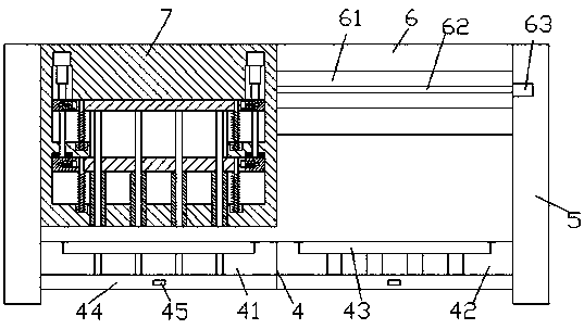
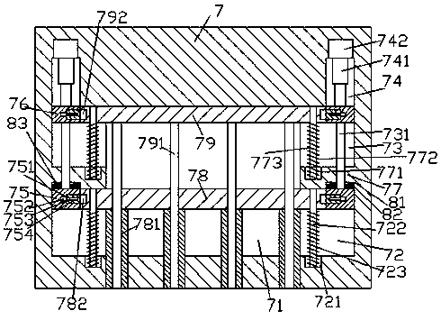
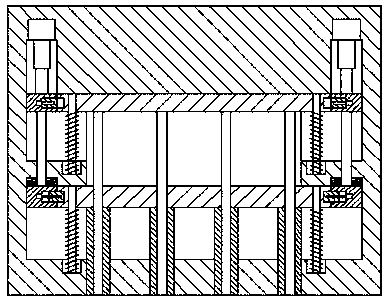
[0025] Such as Figure 1-Figure 8 As shown, a practical iron plate cutting device for construction engineering of the present invention includes a base frame and a cutting device 7, and a cavity 71 is provided inside the cutting device 7, and the left and right sides of the cavity 71 are oppositely provided with a second A chute 73, a fence 77 and a second chute 72, the cavity 71 is provided with a left and right extended first slide bar 79, and the left and right extended tail ends of the first slide bar 79 penetrate into the left and right sides respectively The first chute 73 of the first chute 73 is slidingly connected, and the second sliding rod 78 extending left and right is provided under the cavity 71, and the left and right extending tail ends of the second sliding rod 78 are inserted into the left and right sides The second chute 72 is slip-fitted and connected, and the bottom of the second slide bar 78 is provided with an annular stamping bar 781 extending downwards...


PUM


Abstract

The invention discloses a practical iron plate cutting device for constructional engineering. The practical iron plate cutting device comprises a base frame and a cutting device. A cavity is formed inthe cutting device. First sliding grooves, railing plates and second sliding grooves are oppositely arranged on the left side and the right side of the cavity. A first sliding rod extending left andright is arranged above the cavity. The left extending tail end and the right extending tail end of the first sliding rod stretch into the first sliding grooves in the left side and the right side correspondingly and are connected with the first sliding grooves in a sliding fit manner. A second sliding rod extending left and right is arranged below the cavity. The left extending tail end and the right extending tail end of the second sliding rod stretch into the second sliding grooves in the left side and the right side correspondingly and are connected with the second sliding grooves in a sliding fit manner. Circular ring punching rods extending downwards and penetrating the bottom of the cutting device are arranged at the bottom of the second sliding rod. A circular piece punching rod extending up and down is connected in each circular ring punching rod in a sliding fit manner. The practical iron plate cutting device is simple in structure, reasonable in design and convenient to operate, cutting of circular pieces and circular rings can be automatically controlled and switched, the work efficiency is improved, and the manufacturing cost and maintenance cost are low.

Description

technical field [0001] The invention relates to the field of construction engineering, in particular to a practical iron plate cutting device for construction engineering. Background technique [0002] The iron plate is the material for cutting rings and discs. The iron rings and iron sheets formed by cutting have a wide range of uses in construction projects. The existing cutting technology still mainly uses manual hand-held cutting machines to cut on the iron plate with the line drawn. , the cut circle is not standard enough, time-consuming and labor-intensive, and of low quality. Some stamping and cutting machines only have a single mode, or can only form rings, or can only form discs, which is poor in practicability. Contents of the invention [0003] The technical problem to be solved by the present invention is to provide a practical iron plate cutting device for construction engineering, which can solve the above-mentioned problems in the prior art. [0004] The pr...

Claims


Application Information

Patent Timeline
IPC IPC(8): B21D28/00B21D28/14
CPCB21D28/00B21D28/14
Inventor 吴俊
Owner 广州尚儒自控系统工程有限公司
Why Eureka
Try Eureka