An oil circuit distribution valve for large flow hydraulic system

A hydraulic system and oil circuit distribution technology, applied in the field of hydraulic valves, can solve the problems of high price, increased cost of electronic control, system complexity, and cost pressure, and achieve the effect of compact size, simple structure, and reduced difficulty and cost

Active Publication Date: 2020-04-21
南通东海机床制造集团有限公司
View PDF10 Cites 0 Cited by
  • Summary
  • Abstract
  • Description
  • Claims
  • Application Information

AI Technical Summary

Problems solved by technology

The disadvantages in the existing oil circuit are: (1) the price of each electro-hydraulic proportional multi-way valve is expensive, the market price is 3000-4000 yuan, and there is cost pressure for mechanical equipment with low price; Each electro-hydraulic proportional valve must be equipped with an amplifier or controller, and the selection of multiple electro-hydraulic proportional valves also increases the cost of electronic control and the complexity of the system

Method used


Image

  • An oil circuit distribution valve for large flow hydraulic system
  • An oil circuit distribution valve for large flow hydraulic system
  • An oil circuit distribution valve for large flow hydraulic system

Examples


Embodiment Construction

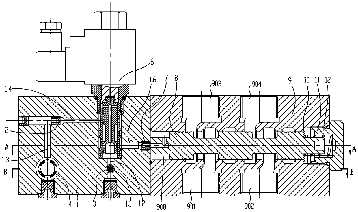
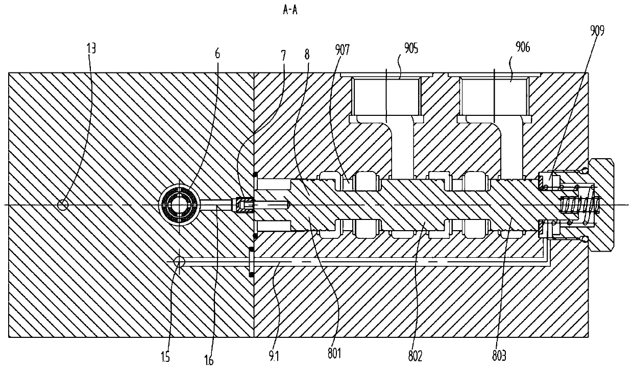
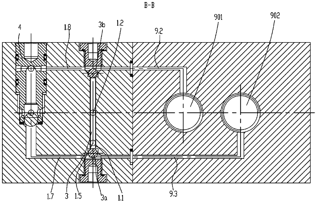
[0021] see Figure 1-6 , the present invention provides an oil distribution valve for a large flow hydraulic system, including a P1 oil port 901, a P2 oil port 902, an A oil port 903, a B oil port 904, a C oil port 905, and a D oil port 906 The valve body 9 is provided with a left and right through installation hole 907 in the valve body 9, and the main valve core 8 for controlling the on-off of the oil port is slidably connected in the installation hole 907; on the side of the main valve core 8 A first shoulder 801, a second shoulder 802, and a third shoulder 803 are sequentially provided along its axial direction from left to right, and an end cover 1 is installed on the left end of the mounting hole 907 on the valve body 9, so that A control cavity 908 is formed between the first shoulder 801 and the end cover 1; a screw plug 12 is installed on the right end of the installation hole 907 on the valve body 9, and the third shoulder 803 and the screw The oil return cavity 909...


PUM


Abstract

The invention discloses an oil path distribution valve for a large-flow hydraulic system. The oil path distribution valve comprises a valve body which is provided with an oil port P1, an oil port P2,an oil port A, an oil port B, an oil port C and an oil port D, wherein a mounting hole is formed in the valve body, and a main valve element is slidably connected in the mounting hole; a first shoulder, a second shoulder and a third shoulder are arranged on the side face of the main valve element, an end cover is arranged at the position, located at the left end of the mounting hole, of the valvebody, and a control cavity is formed between the first shoulder and the end cover; a plug is arranged at the position, located at the right end of the mounting hole, of the valve body, and an oil return cavity is formed between the third shoulder and the plug; a spring which is used for forcing the main valve element to move leftwards is arranged in the oil return cavity, one end of the spring abuts against the right end of the main valve element, and the other end of the spring abuts against the plug; and a two-position three-way electromagnetic valve, a low-pressure selection assembly and ashuttle valve assembly are arranged on the end cover. The oil path distribution valve is simple in structure, compact in size and convenient to install, and is capable of achieving the distribution function of a hydraulic oil path.

Description

technical field [0001] The invention relates to the technical field of hydraulic valves, in particular to an oil circuit distribution valve used in a large-flow hydraulic system. Background technique [0002] In modern industrial hydraulic and mobile machinery hydraulic oil circuits, a large number of identical actuators (hydraulic cylinders or hydraulic motors) are used in parallel and sequentially acting oil circuits. Such as Image 6 As shown, in the existing hydraulic system, the corresponding number of electro-hydraulic proportional multi-way valves is generally selected according to the number of actuators to control the actuators. The disadvantages in the existing oil circuit are: (1) the price of each electro-hydraulic proportional multi-way valve is expensive, the market price is 3,000-4,000 yuan, and there is cost pressure on mechanical equipment with low price; (2) Each electro-hydraulic proportional valve must be equipped with an amplifier or controller, and the...

Claims


Application Information

Patent Timeline
Patent Type & Authority Patents(China)
IPC IPC(8): F15B13/02F16K11/07F16K27/04
CPCF15B13/02F16K11/07F16K27/041
Inventor 陈艳艳
Owner 南通东海机床制造集团有限公司
Why Eureka
Try Eureka