Node device for LED lighting control network and LED lighting network topology

A network topology, lighting control technology, applied in lighting devices, energy-saving control technology, lamp circuit layout, etc., can solve the problems of small number of driving nodes, out-of-control large nodes, short driving distance, etc. The effect of easy load and reduced workload

Active Publication Date: 2015-07-29
驻马店韵光科技有限公司
View PDF6 Cites 0 Cited by
  • Summary
  • Abstract
  • Description
  • Claims
  • Application Information

AI Technical Summary

Problems solved by technology

[0007] In view of the above-mentioned shortcomings of the prior art, the object of the present invention is to provide a node device for the LED lighting control network and a topology structure of the LED lighting network, which is used to solve the problem of the small number of driving nodes and the problem of driving the LED lighting control system in the prior art. Problems such as short distance, large number of cable cores, small data flow, and chain network topology. A node failure causes a large number of nodes to go out of control, etc.

Method used


Image

  • Node device for LED lighting control network and LED lighting network topology
  • Node device for LED lighting control network and LED lighting network topology
  • Node device for LED lighting control network and LED lighting network topology

Examples


Embodiment 1

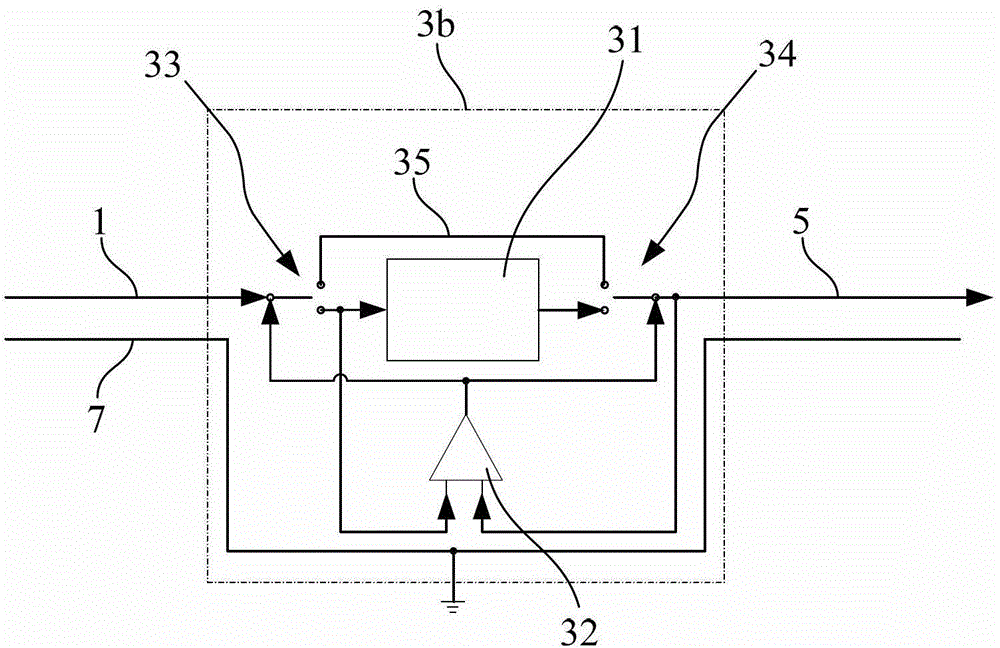
[0058] see figure 2 , which is a schematic diagram of the architecture of the node device used in the LED lighting control network according to the present invention. As shown in the figure, the present invention provides a node device 3b for LED lighting control network, one end of which is connected to the signal input line 1, and the other end is connected to the signal output line 5. In this embodiment, the node device 3b is used for Analyzing the control instructions to respectively control each LED light module to perform lighting, extinguishment, brightness adjustment or color temperature adjustment operations and to monitor and feed back the working status of each LED light module controlled by it to the control center. The node device 3 b at least includes: a signal codec module 31 , a discrimination module 32 , a first bypass switch 33 , a second bypass switch 34 , and a straight-through cable 35 .

[0059] The signal encoding and decoding module 31 is used to anal...

Embodiment 2

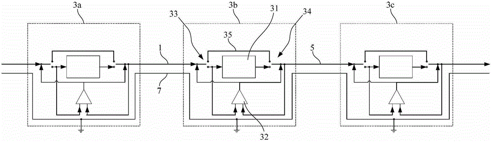
[0072] The present invention also provides a LED lighting network topology based on the above node devices, including: a signal input line 1 , a plurality of node devices 3 a , 3 b , and 3 c , a signal output line 5 , and a ground line 7 .

[0073] Each node device 3 a , 3 b , or 3 c includes: a signal codec module 31 , a discrimination module 32 , a first bypass switch 33 , a second bypass switch 34 , and a straight-through cable 35 .

[0074] The signal encoding and decoding module 31 is used to analyze after receiving the data packet sent by the signal input line 1, and extract the data matching its own address to generate the same data format as the data packet, as The regenerated data packet is output through the signal output line 5; in other words, the signal codec module 31 analyzes after receiving the data packet carrying the control command, leaving a data string matching its own address, and converting the data string of the following node After the data string is r...


PUM


Abstract

The invention provides node devices for an LED (light-emitting diode) light control network and an LED light network topology. The node devices and the network topology have the following beneficial effects: each node can automatically monitor the respective input / output state and has a signal bypassing function; once signals interrupt abnormally, bypass devices are immediately started, the nodes are separated from the network and the signals are directly connected to the following stage; because of the chained network topology, each node only communicates with the two adjacent nodes, so the signal drive capacity is greatly improved and longer distances and more nodes can be driven; and the quantity of the needed cable cores is small and the data traffic is large, so the automatic address allocation function can be achieved, thus greatly reducing the workload of construction.

Description

technical field [0001] The invention relates to the field of system control of LED lamps, in particular to a node device for LED lighting control network and a topology structure of the LED lighting network. Background technique [0002] As an emerging energy-saving light source, LED light source has been paid more and more attention by people. There are various control systems for LED, but the core technology of its communication is nothing more than the following three: [0003] One: The communication control scheme based on the RS485 physical bus, including the most common DMX512 bus products on the market, all belong to this category. see figure 1 , is shown as a schematic diagram of the LED control system network in the prior art, as shown in the figure, it includes a plurality of nodes 23, and each node includes a bus transceiver terminal 20, an input line 21 and an output line 22, and the input line 21 and the output line 22 are respectively connected to a pair of a...

Claims


Application Information

Patent Timeline
Patent Type & Authority Patents(China)
IPC IPC(8): H05B37/02H04L12/28
CPCY02B20/42Y02B20/40
Inventor 刘群温源傅铭高建斌张永旭
Owner 驻马店韵光科技有限公司
Why Eureka
Try Eureka