Mixed type stepping motor

A stepping motor, hybrid technology, applied in the direction of electrical components, electromechanical devices, magnetic circuit rotating parts, etc., can solve the problems of motor characteristics degradation, unusability, magnetic balance deterioration, etc., and achieve unbalanced reduction of pressing force Small, highly reliable effect

Inactive Publication Date: 2013-01-30
SHINANO KENSHI
View PDF6 Cites 0 Cited by
  • Summary
  • Abstract
  • Description
  • Claims
  • Application Information

AI Technical Summary

Problems solved by technology

[0009] (1) In order to prevent the magnetic short circuit between the rotor cores, a non-magnetic cylindrical spacer is required. Since the cylindrical spacer does not contribute to the magnetic circuit, it becomes a useless space where the rotor core cannot be placed.
[0010] (2) In addition, even if the rotor is omitted Image 6 In the case of the cylindrical partitions shown in the figure, multiple layers are arranged, and since the rotor has the rotor core stacked on both sides of the rotor magnet with the rotor shaft as the center, and a plurality of such rotors are installed, if the accuracy of the assembly tool is poor , the position accuracy of the pole teeth of each rotor core will deteriorate, which will have a bad influence on the characteristics of the motor
[0011] (3) In addition, when the rotor shaft 54 ​​is pressed into the rotor cores 51, 52 and the rotor magnet 53, a deviation occurs be...

Method used


Image

  • Mixed type stepping motor
  • Mixed type stepping motor
  • Mixed type stepping motor

Examples


Embodiment Construction

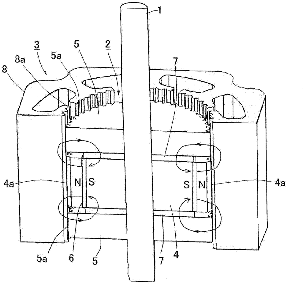
[0037] Hereinafter, an example of the hybrid stepping motor according to the present invention will be described with reference to the drawings. figure 1 An explanatory diagram showing a cross-section of a hybrid stepping motor.

[0038] The hybrid stepping motor includes: a rotor 2 mounted on a rotor shaft 1, and a rotor magnet disposed in a rotor core having rotor pole teeth formed on an outer peripheral surface; and a stator 3 mounted on the rotor pole A magnetic path is formed between the teeth and stator pole teeth of a stator core on which coils are wound. By energizing the coil, a rotational force acts between the rotor teeth and the opposing stator teeth to rotate. The specific description will be given below.

[0039] exist figure 1 In the following, the structure of the rotor 2 will be described first.

[0040] Provided are: a first rotor core 4 that is centered on the rotor shaft 1 and has first rotor pole teeth 4a formed at predetermined pitches in the circumfe...


PUM


Abstract

A mixed type stepping motor can reduce the number of rotor cores when a multi-layer rotor is mounted, and raise assembly efficiency and motor characteristics. The mixed type stepping motor comprises a first rotor core (4) which is arrange around a rotor shaft (1) and provided with a first rotor polar tooth (4a) on the outer circumference surface; a first rotor magnet (6) arranged concentric with the rotor shaft (1) near the first rotor polar tooth (4a); and a second rotor polar tooth (5a) which is laminated across a magnetic body (7) at two sides of the axial direction of the first rotor core (4), arranged around the rotor shaft (1), and provided with a second rotor polar tooth on the outer circumference surface, wherein an axial direction lamination thickness of the first rotor core (4) is bigger than that of the second rotor core (5), a plurality of magnetic circuits are formed simultaneously in the axial direction, and among the magnetic circuits, magnetic flows of the first rotor magnet (6) starts from the first rotor polar tooth (4a), passes through an opposed stator polar tooth (8a), the second rotor core (5) at two sides of the axial direction, and the magnetic body (7), and returns back to the first rotor magnet (6).

Description

technical field [0001] The present invention relates to a hybrid stepping motor used in, for example, copiers, printers, surveillance cameras, ATMs (Automatic Teller Machines) and the like. Background technique [0002] The structure of the hybrid stepping motor is as follows: the rotor cores 51, 52 are formed by laminating toothed iron cores (refer to Figure 5 ), the rotor cores 51 and 52 are mounted on the rotor shaft 54 ​​with the cylindrical rotor magnet 53 sandwiched between them by a half tooth pitch to form a rotor. The rotor magnet 53 is magnetized to N / S poles in a direction parallel to the axial direction. Rotor teeth are formed on the outer peripheries of the rotor cores 51, 52 so as to face the stator teeth 55a of the opposing stator core 55 (see Figure 5 ). Coils (not shown) are wound around the stator teeth 55 a of the stator core 55 . [0003] exist Figure 5 In , the rotor core 51 is magnetized to the N pole, and the rotor core 52 is magnetized to the S p...

Claims


Application Information

Patent Timeline
IPC IPC(8): H02K16/02H02K1/27
Inventor 林千寻王东辉佐藤英信
Owner SHINANO KENSHI
Why Eureka
Try Eureka