
Medical Pendant System

A pendant and brake system technology, applied in the field of medical pendant systems, can solve the problems of not meeting the single failure condition of medical equipment, fixed cable length, and many main control circuit boards, so as to meet the requirements of single failure condition and optimize the circuit Design, easy function integration effect

Active Publication Date: 2017-01-25
MAQUET SUZHOU
View PDF7 Cites 0 Cited by
  • Summary
  • Abstract
  • Description
  • Claims
  • Application Information

AI Technical Summary

Problems solved by technology

[0003] The disadvantages of this solution are: it is not convenient for the user to adjust the position; the number of cables is large, it takes up space, and the length of the cables is fixed; it does not have expansion functions; it is inconvenient to maintain; Failure to meet single failure condition requirements for medical devices

Method used


Image

  • Medical Pendant System
  • Medical Pendant System
  • Medical Pendant System

Examples


Embodiment Construction

[0032] The present invention will be further described below in conjunction with specific embodiment and accompanying drawing, set forth more details in the following description so as to fully understand the present invention, but the present invention can obviously be implemented in many other ways different from this description, Those skilled in the art can roughly generalize and deduce according to actual application situations without violating the connotation of the present invention, so the content of this specific embodiment should not limit the protection scope of the present invention.

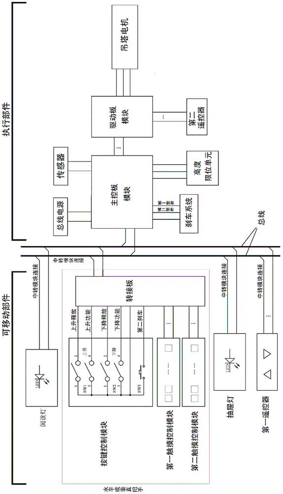
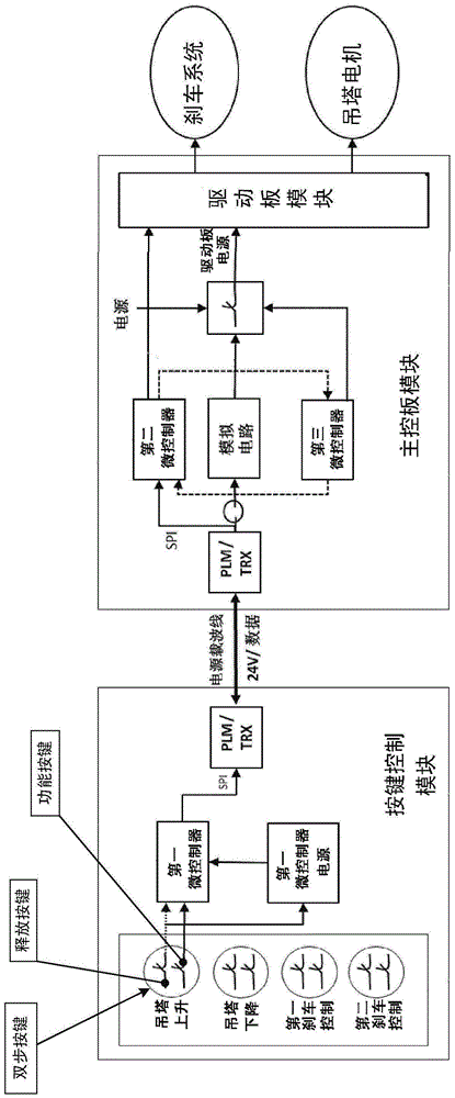
[0033] figure 2 A circuit diagram of a medical pendant system according to an embodiment of the present invention is shown. image 3 A control logic diagram of a medical pendant system according to an embodiment of the present invention is shown.

[0034] The present invention adopts the power carrier wave technology, uses two wires or conductors as the bus carrier, on the one han...


PUM


Abstract

The invention relates to a medical pendant system. The medical pendant system includes movable parts, executive parts and a bus. The movable parts include a button control module, which includes brake system control buttons and pendant lifting control buttons. The executive parts include a main control board module, a drive board module, and a bus power supply. , Pendant motor and brake system, the main control board module is connected to the drive board module, bus power supply and brake system, the drive board module is connected to the pendant motor, the movable parts and executive parts are respectively connected to the bus, and the bus is used to transmit power supply and commands, the pendant lifting control buttons include the pendant up button and the pendant down button, both of which are two-step buttons. The invention can have the following beneficial technical effects: the height direction can be adjusted steplessly without changing the cable length; the number of cable cores is reduced; the circuit design is optimized, easy to install and maintain; it is convenient for function integration and expansion; Failure condition requirements; improved reliability.

Description

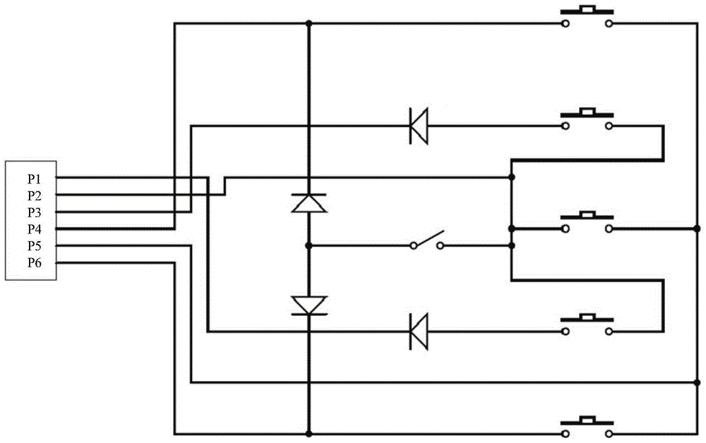
technical field [0001] The invention relates to the technical field of medical equipment, in particular to a medical pendant system. Background technique [0002] The medical pendant is an indispensable medical equipment in the hospital's modern operating room and intensive care unit. The current medical pendant system mainly adopts the following technical solutions: the circuit control part is connected in a fixed position; the line control part is connected one-to-one, and there are several control buttons corresponding to several circuits, see figure 1 ; There are different main control circuits for different applications. [0003] The disadvantages of this solution are: it is not convenient for the user to adjust the position; the number of cables is large, it takes up space, and the length of the cables is fixed; it does not have expansion functions; it is inconvenient to maintain; Does not meet the single failure condition requirements for medical devices. Contents...

Claims


Application Information

Patent Timeline
Patent Type & Authority Patents(China)
IPC IPC(8): A61B90/00A61G12/00
CPCA61G12/002
Inventor 詹升平黄家胜张伟张远杰黎群华李红强吉鸣
Owner MAQUET SUZHOU
Learn More