Cable bridge stand

A cable and bridge technology, which is applied in the field of cable installation, can solve the problems of disorderly distribution of cables and inconvenient cable maintenance.

Inactive Publication Date: 2018-07-06
青岛鹏渤钢结构有限公司
View PDF9 Cites 11 Cited by
  • Summary
  • Abstract
  • Description
  • Claims
  • Application Information

AI Technical Summary

Problems solved by technology

[0004] However, when there are many cables in the installation slot, the cables will be scattered

Method used


Image

  • Cable bridge stand
  • Cable bridge stand
  • Cable bridge stand

Examples


Embodiment Construction

[0028] The present invention will be described in further detail below in conjunction with the accompanying drawings. Wherein the same components are denoted by the same reference numerals. It should be noted that the words "front", "rear", "left", "right", "upper" and "lower" used in the following description refer to the directions in the drawings, and the words "bottom" and "top "Face", "inner" and "outer" refer to directions toward or away from, respectively, the geometric center of a particular component.

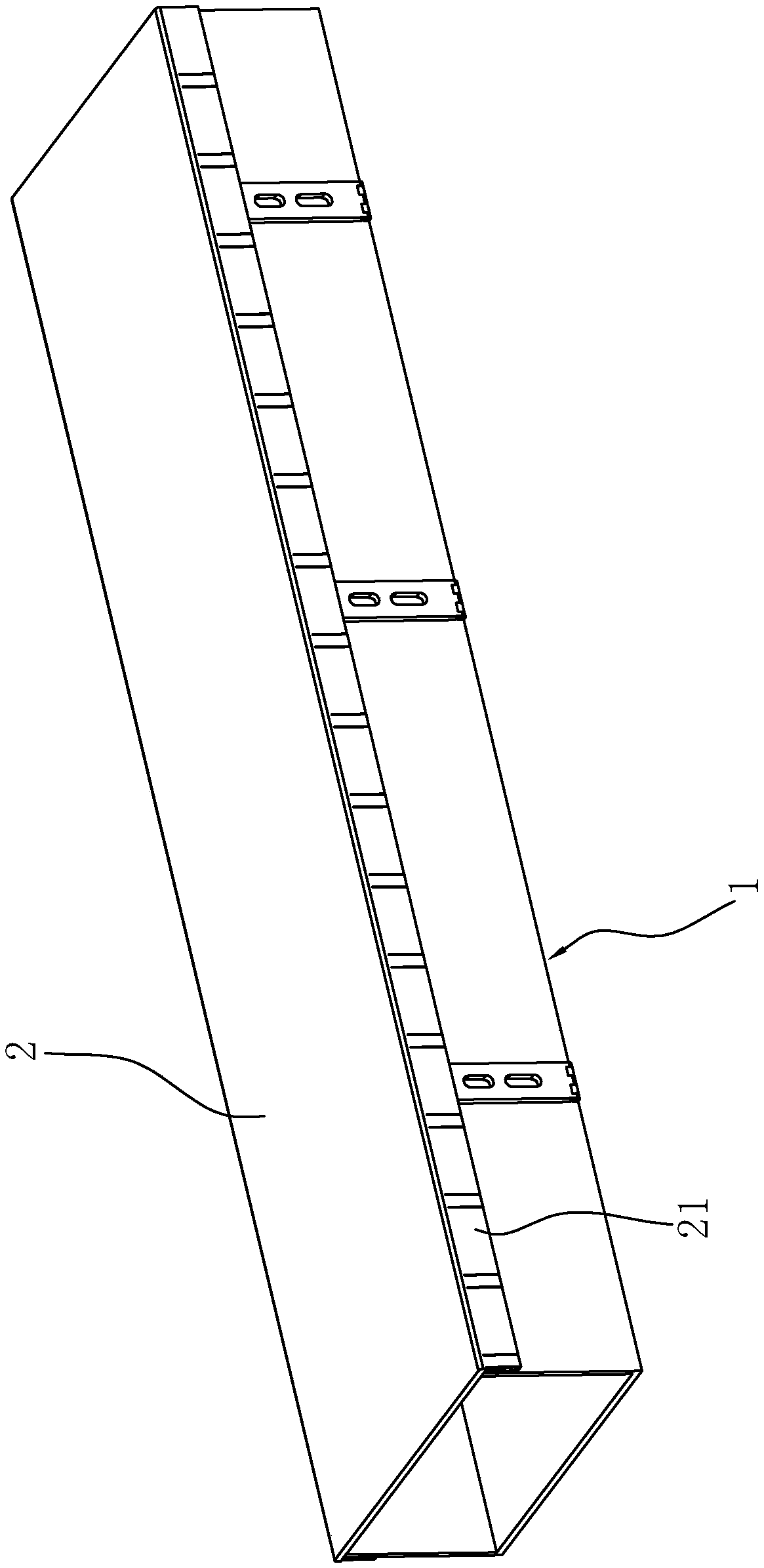
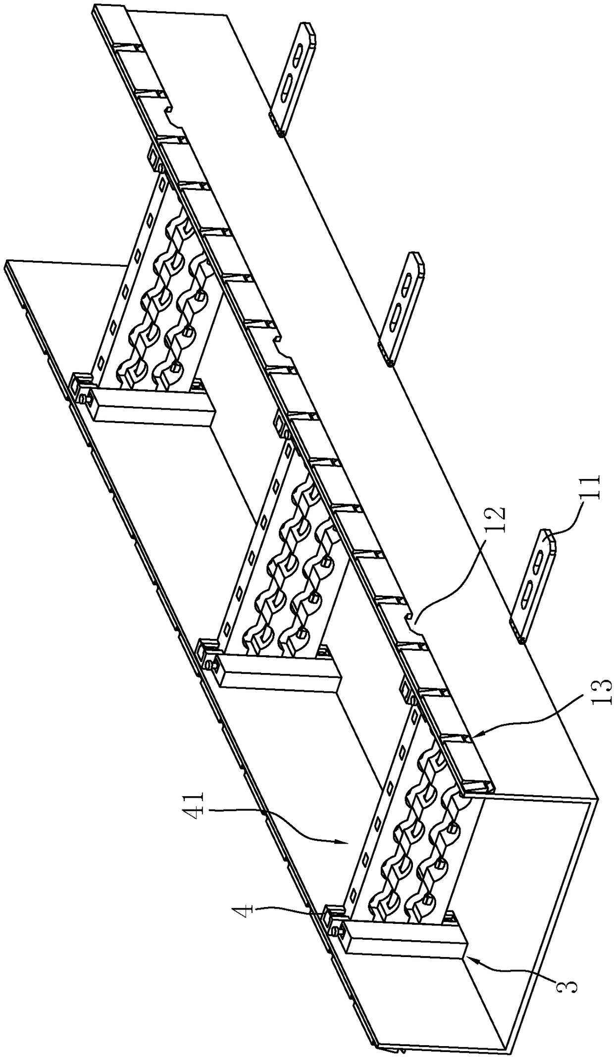
[0029] A cable tray, such as figure 1 and figure 2 As shown, it includes a "U"-shaped mounting plate 1, a clamping plate 2 clamped with the top of the "U"-shaped mounting plate 1, a number of fixed bridge frames 3 fixed on the inner wall of the "U"-shaped mounting plate 1, and a fixed bridge frame. 3 snap-connected mobile bridge frame 4.

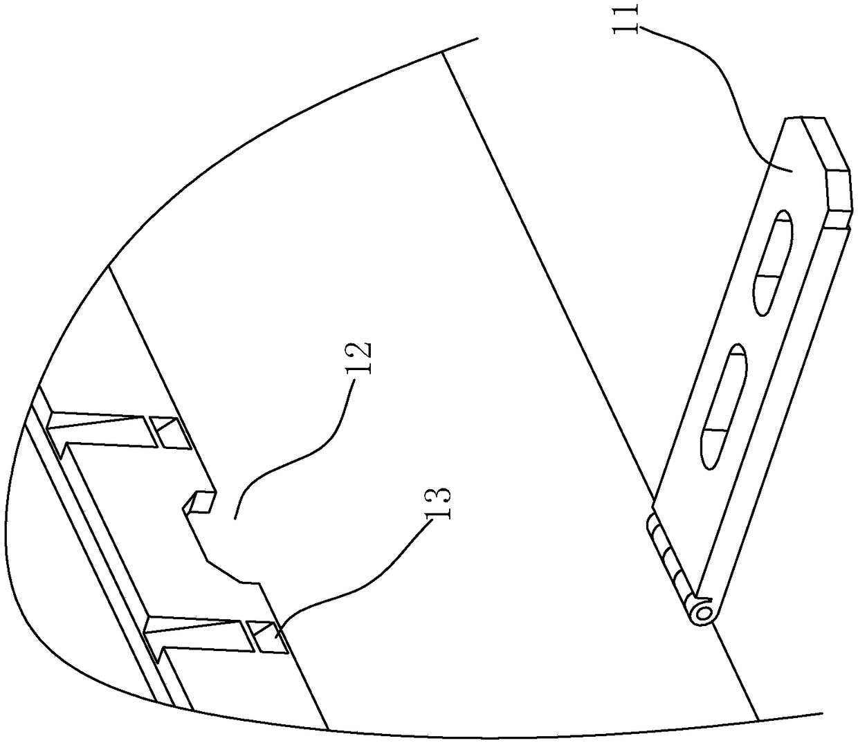
[0030] Such as figure 2 and image 3 As shown, the top of the "U"-shaped mounting plate 1 is provided with a connecting gro...


PUM


Abstract

The invention discloses a cable bridge stand. The cable bridge stand comprises a U-shaped mounting board and a clamping board clamped with the U-shaped mounting board, wherein the U-shaped mounting board is internally fixedly connected with multiple fixed bridge frames and multiple moving bridge frames clamped with the fixed bridge frames, and the moving bridge frames are internally provided withbranching assemblies used for clamping cables through approaching or keeping away from the cables. The cables are arranged in branching slots in fixed branching boards, branching of the cables in theU-shaped mounting board is carried out, through clamping of the moving bridge frames and the fixed bridge frames, the cables are arranged in the U-shaped mounting board, the cables in the U-shaped mounting board are neatly placed, and the cables in the U-shaped mounting board are overhauled.

Description

technical field [0001] The invention relates to the field of cable installation, in particular to a cable bridge. Background technique [0002] A cable tray is a cable laying device used to guide and accommodate cables. [0003] The existing cable tray includes an installation slot plate and a cover plate snapped to the top of the installation slot plate, and cables are placed in the installation slot plate. [0004] However, when there are many cables for installing the slot plate, the cables will be scattered in the installation slot plate, making it inconvenient to overhaul the cables in the installation slot plate. Contents of the invention [0005] The object of the present invention is to provide a cable bridge, which has the advantage of being able to branch the cables in the "U"-shaped mounting plate, so as to facilitate the maintenance of the cables in the "U"-shaped mounting plate. [0006] The above object of the present invention is achieved through the follo...

Claims


Application Information

Patent Timeline
IPC IPC(8): H02G3/04
CPCH02G3/0437H02G3/0456
Inventor 刘全涛
Owner 青岛鹏渤钢结构有限公司
Why Eureka
Try Eureka