Injection mold for thin-walled deep-cavity electromechanical shell

An injection mold and deep cavity technology, which is applied in the field of injection molds for thin-walled deep-cavity electromechanical housings, can solve the problems of complex molding process and increased molding difficulty, achieve simple and reasonable structural design, improve mold life, and improve company benefits.

Pending Publication Date: 2018-07-10
SHANDONG UNIV OF SCI & TECH
View PDF0 Cites 1 Cited by
  • Summary
  • Abstract
  • Description
  • Claims
  • Application Information

AI Technical Summary

Problems solved by technology

[0002] At present, conventional injection molded parts can be molded using conventional injection molding methods and ordinary plastics. The molding process is familiar to people, and the molds have also been standardized. However, thin-walled deep cavity injection molded parts are not, because as the wall thickness decreases, the plastic melt in the mold The cooling speed in the cavity is accelerated, and it will solidify in a short time. Therefore, the molding of thin-walled deep cavity injection molded parts must use a high injection pressure to inject a resin with high temperature and good fluidity at high speed in a short period of time. Pressed into the cavity, which makes the molding process extremely complicated and difficult to form, so the mold design is very important when molding thin-walled deep-cavity injection molded parts. When forming thin-walled deep-cavity injection molded parts, special molds for thin-walled deep-cavity injection molded parts need to be specially designed.

Method used


Image

  • Injection mold for thin-walled deep-cavity electromechanical shell
  • Injection mold for thin-walled deep-cavity electromechanical shell
  • Injection mold for thin-walled deep-cavity electromechanical shell

Examples


Embodiment example

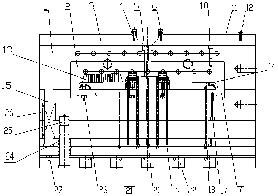
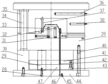
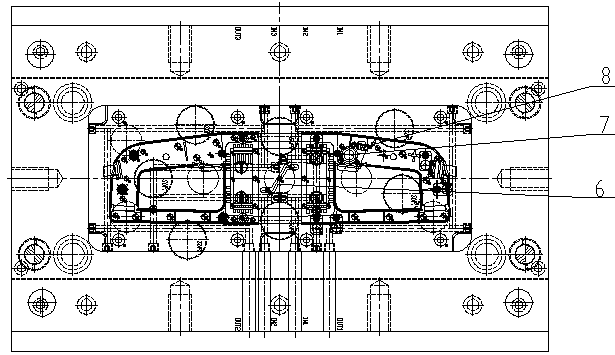
[0020] Specific examples of the invention Figure 1 to Figure 4 As shown, in actual use, first install the insert 8 and insert 23 on the back mold core 16, and then install the rear mold core 16 on the movable template 39; then install the second insert 37 on the front mold core 2. Then install the front mold core 2 on the fixed template 1 to close the front and rear mold cores to complete the mold clamping. Fix the mold on the injection molding machine, inject cooling water through the water injection port to form a water circulation in the cooling water channel, then turn on the injection molding machine, and inject the material into the cavity through the nozzle 5 by side pouring. After the injection molding is completed, The movable mold side goes down, and the push rod pushes the thimble support plate 47 through the KO hole 22, thereby driving thimble 18, thimble 2 19, thimble 3 20, thimble 4 21 and cylinder 42 to move up, eject the injection molded part, and finally in th...


PUM


Abstract

The invention discloses an injection mold for a thin-walled deep-cavity electromechanical shell. The injection mold comprises a fixed mold side, a movable mold side and a cooling system of the injection mold. The fixed mold side is provided with a fixed plate and a fixed mold plate, and the movable mold side is provided with a movable mold plate, a supporting plate, a base plate and a movable moldseat plate. The injection mold has a one-mold two-cavity structural mode, and the cooling system of the injection mold is provided with a well at the position of a deep cavity of the electromechanical shell so as to ensure balanced cooling. The mold adopts a side pouring mode, cool material wells are arranged at the tail ends of a main runner and a sub-runner, and the circumstance that cool materials enter a cavity to affect the quality of plastic parts is prevented. By the injection mold, according to the structural characteristics of thin-walled deep-cavity plastic parts and on the basis ofa traditional structural mode of a mold, the dimensional stability of an injection parts is ensured effectively, moreover, shrinkage and warping influences are controlled in a specified range, and the quality of products is improved.

Description

Technical field [0001] The invention relates to the field of design and manufacture of injection molds, in particular to a thin-walled deep cavity electromechanical shell injection mold. Background technique [0002] At present, conventional injection molded parts can be molded using conventional injection molding methods and ordinary plastics. The molding process is familiar to people and the mold has been standardized. However, thin-walled deep cavity injection molded parts are not, because as the wall thickness decreases, the plastic melt is in the mold. The cooling rate in the cavity is accelerated, and it will solidify in a short time. Therefore, the molding of thin-walled deep-cavity injection molded parts must be made with high injection pressure in a short time to achieve high material temperature and high fluidity resin. Press into the cavity, which makes the molding process extremely complicated and difficult to mold. Therefore, mold design is very important when formin...

Claims


Application Information

Patent Timeline
IPC IPC(8): B29C45/27B29C45/32B29C45/40B29C45/73
CPCB29C45/27B29C45/32B29C45/4005B29C45/73B29C2045/2683
Inventor 韩以伦李志恒梁彦高郭唤唤郑辉鲁其兴侯磊李明波
Owner SHANDONG UNIV OF SCI & TECH
Why Eureka
Try Eureka