Gear device used for railway vehicle

A technology for gear devices and railway vehicles, which is applied to transmission parts, gear lubrication/cooling, belts/chains/gears, etc., which can solve the problem of low degrees of freedom of gear devices and achieve the effect of increasing degrees of freedom

Pending Publication Date: 2018-07-10
TOYO DENKI SEIZO KK
View PDF12 Cites 3 Cited by
  • Summary
  • Abstract
  • Description
  • Claims
  • Application Information

AI Technical Summary

Problems solved by technology

Therefore, if the gear box is formed like the above-mentioned conventional example, the portion of the gear box that defines the oil storage chamber may interfere with other components or devices arranged on the trolley, and there is freedom in the design of the gear device. low degree problem

Method used


Image

  • Gear device used for railway vehicle
  • Gear device used for railway vehicle
  • Gear device used for railway vehicle

Examples


Embodiment Construction

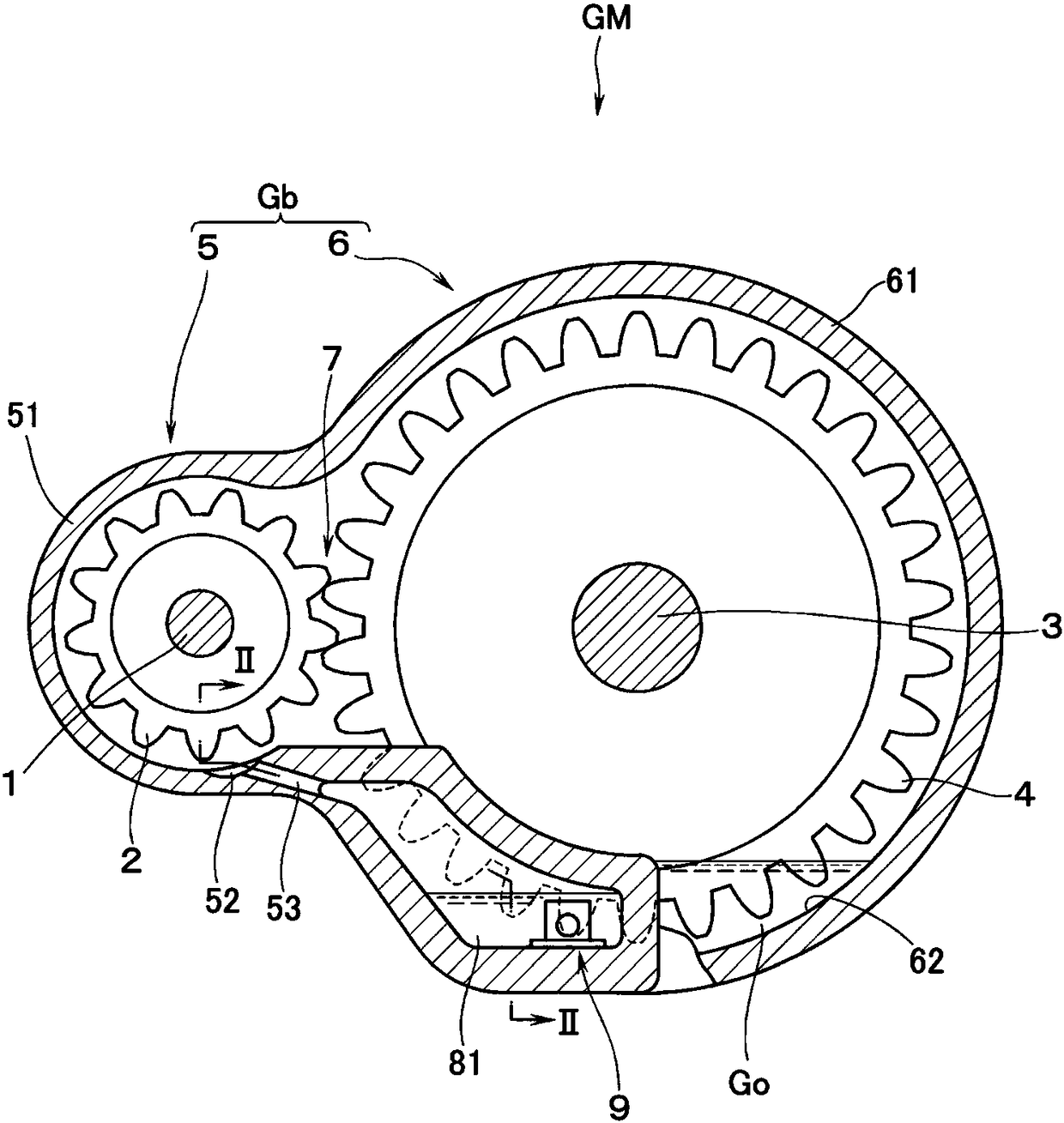
[0015] Hereinafter, embodiments of the gear device for railway vehicles according to the present invention will be described with reference to the drawings. In the following, the installation posture on the trolley is indicated figure 1 As a reference, terms representing directions such as "up" and "down" are used.

[0016] refer to figure 1 , GM is the gear device for railway vehicles according to this embodiment. The gear unit GM includes the gear case Gb of the carriage provided outside the drawing. In the gearbox Gb, a pinion gear 2 fixed to an input shaft 1 of an unillustrated electric motor (drive source) via a bearing (not shown) and a large gear 4 fixed to an axle 3 via a bearing (not shown) are connected to each other. In a horizontally engaged state, the pinion gear 2 and the bull gear 4 are accommodated. Well-known components and elements can be used other than the gear case Gb constituting the gear unit GM, and therefore detailed description including these wil...


PUM


Abstract

The invention provides a gear device used for a railway vehicle. The gear device comprises a gear case. In the gear case, a pinion and a rack wheel are held in a state that the pinion and the rack wheel are meshed with each other in a horizontal direction, and the gear case is internally provided with an oil storage cavity soaking the lower part of the rack wheel. A function of guiding a part of lubricating oil splashed by rotation of the rack wheel into an oil accumulation cavity would not be damaged. An outlet space is formed on the lower part of a part of the gear case which has an accommodation space for the pinion. The gear case (Gb) is configured that a small case portion (5) which has an accommodation space for the pinion (2) and a large case portion (6) which has an accommodation space for the rack wheel are continuously arranged on a horizontal direction, the small case portion has an arc peripheral wall, and the peripheral wall surrounds the pinion part which has special interval relative to a meshing portion of the rack wheel on a peripheral direction. The oil accumulation cavity (81) is arranged on the side surface of the axial direction of the large case portion in a protruded manner, and is lower than the pinion. The inner surface bottom of the small case portion is provided with an oil accommodation groove (52) which receives lubricating oil (Go), and is providedwith a communicating path (53) which communicates the oil accumulation cavity with the oil accommodation groove.

Description

technical field [0001] The present invention relates to a gear device for a railway vehicle, which includes a gear box in which the pinion gear fixed to the input shaft of the driving source and the large gear fixed to the axle shaft are housed in a horizontally engaged state with each other. The pinion and the bull gear have an oil storage chamber impregnating the lower part of the bull gear in the gear case. Background technique [0002] Such a gear device for railway vehicles is known in Patent Document 1, for example. The gear unit for railway vehicles further includes: an oil storage chamber for storing a part of the lubricating oil splashed from the oil storage chamber with the rotation of the large gear; and a mechanism for returning the lubricating oil in the oil storage chamber to the oil storage chamber An oil return passage, and an on-off valve that opens and closes the oil return passage. In addition, it is possible to freely adjust the amount of oil in the oil...

Claims


Application Information

Patent Timeline
IPC IPC(8): F16H57/04F16H57/02
CPCF16H57/02F16H57/0452F16H2057/02039
Inventor 石井一弥
Owner TOYO DENKI SEIZO KK
Why Eureka
Try Eureka