A polarization imaging device and method

A polarized imaging and polarized image technology, applied in nonlinear optics, instruments, optics, etc., can solve the problem of insufficient compactness of the polarized imaging device, and achieve the effects of compact structure, convenient operation, and convenient image acquisition

Inactive Publication Date: 2018-07-10
SUPERD CO LTD
View PDF12 Cites 5 Cited by
  • Summary
  • Abstract
  • Description
  • Claims
  • Application Information

AI Technical Summary

Problems solved by technology

[0005] The purpose of the technical solution of the present invention is to provide a polarization imaging device and method without setting a polarizer and a driving structure f

Method used


Image

  • A polarization imaging device and method
  • A polarization imaging device and method
  • A polarization imaging device and method

Examples


Example Embodiment

[0034] In order to make the technical problems, technical solutions, and advantages to be solved by the embodiments of the present invention clearer, a detailed description will be given below with reference to the drawings and specific embodiments.
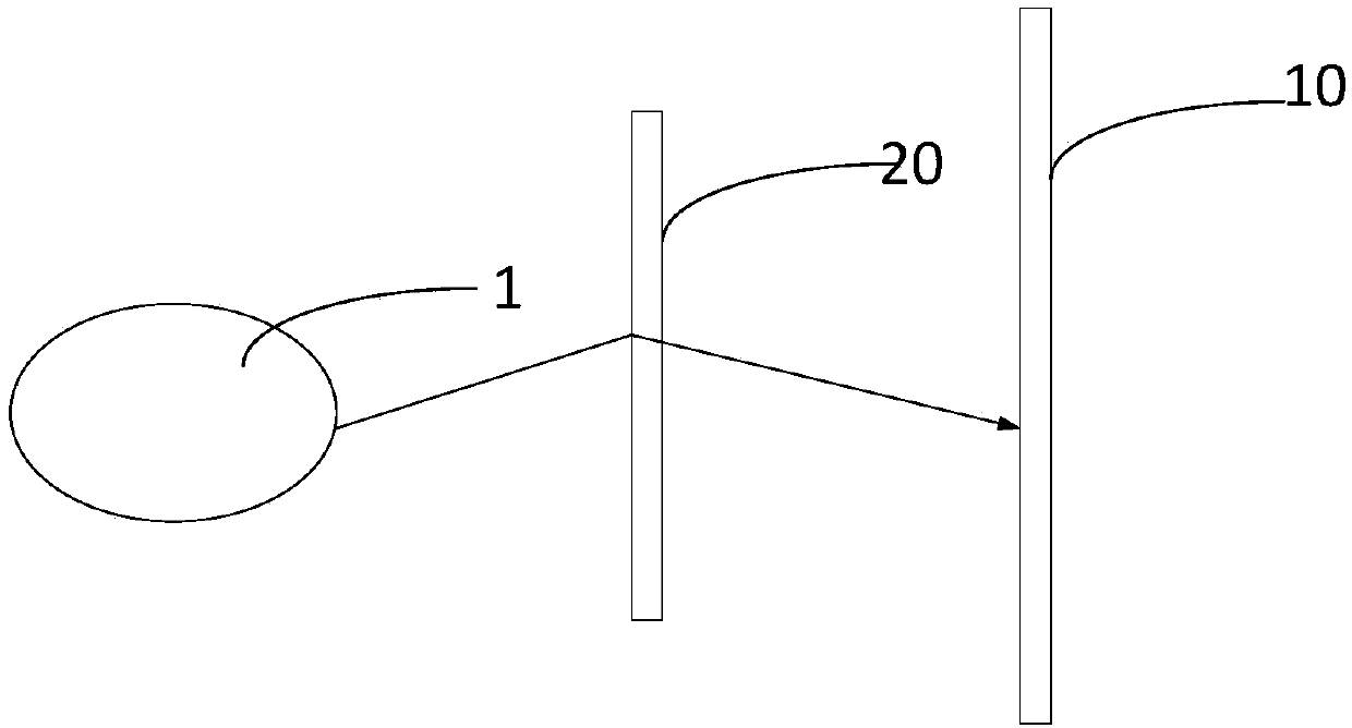
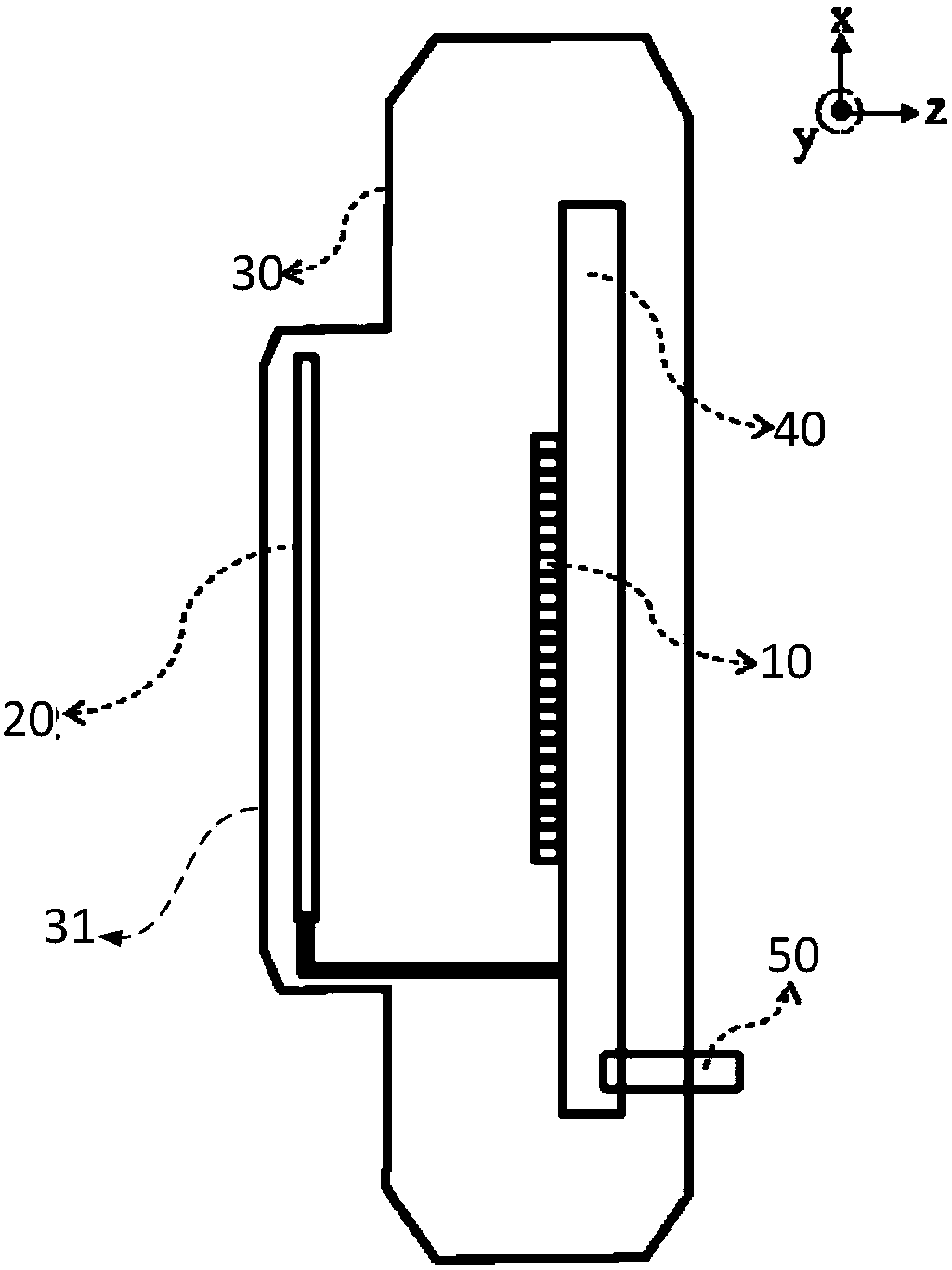
[0035] The embodiment of the present invention provides a polarization imaging device, such as figure 1 versus figure 2 As shown, the polarization imaging device includes:

[0036] Image sensor 10;

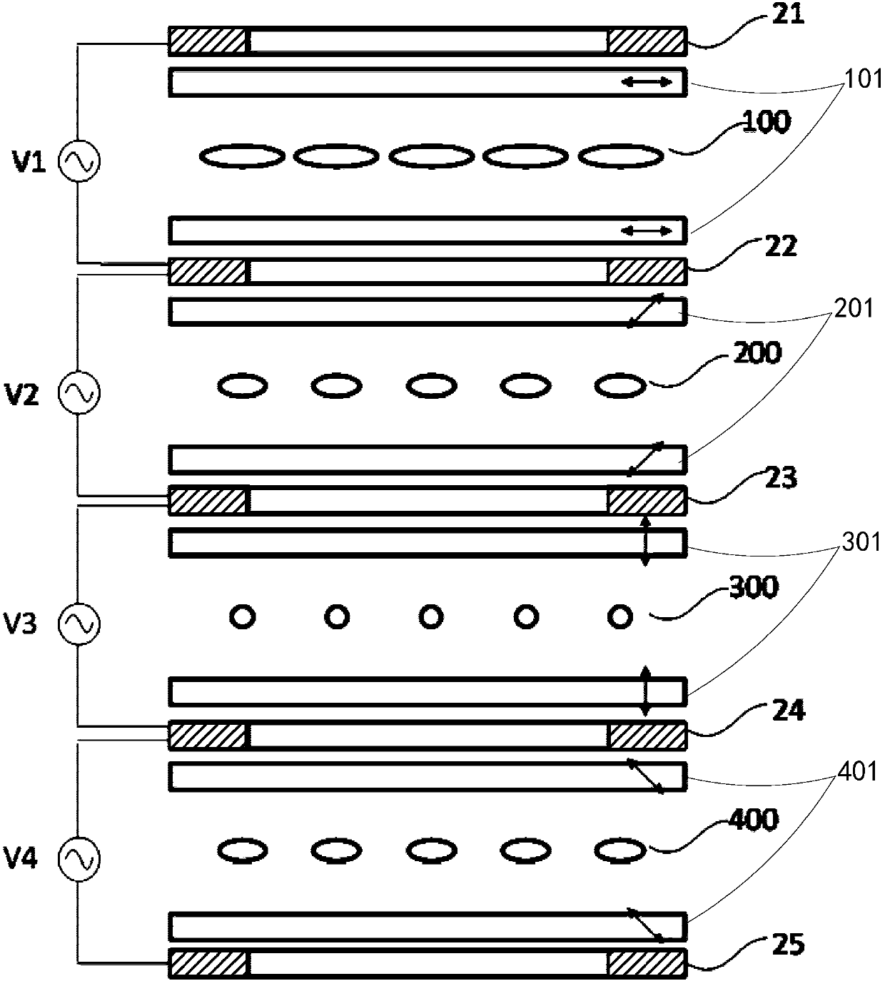
[0037] The liquid crystal lens 20 is arranged between the target object 1 to be imaged and the image sensor 10. The liquid crystal lens 20 includes at least three liquid crystal layers parallel to each other, an electrode layer and an alignment layer adapted to each liquid crystal layer. One liquid crystal layer corresponds to the orientation angle of one orientation layer, and the orientation angles are different from each other; in addition, the liquid crystal lens 20 also includes a voltage drive circuit, and each electrode layer matchi...


PUM

PropertyMeasurementUnit
Thicknessaaaaaaaaaa

Abstract

The invention provides a polarization imaging device and a polarization imaging method of the polarization imaging device. The polarization imaging device comprises a liquid crystal lens and an imagesensor which are arranged oppositely. The liquid crystal lens comprises at least three liquid crystal layers which are parallel to one another and alignment layers and electrode layers matching the liquid crystal layers, wherein each liquid crystal layer is corresponding to the alignment angle of one alignment layer and the alignment angles are different from one another. The liquid crystal lens also comprises a voltage drive circuit which independently controls drive voltage applied to each liquid crystal layer. When the voltage drive circuit applies drive voltage to each layer of the liquidcrystal lens, the focal lengths of the liquid crystal lens units formed by the liquid crystal layers are the same. The device is provided with multiple liquid crystal layers and a polarizing film anda drive structure for adjusting the polarization direction of the polarizing film are not needed, so that the problem that the structure of a polarization imaging device in the prior art is not compact enough is solved.

Description

technical field [0001] The present invention relates to the technical field of polarization imaging, in particular to a polarization imaging device and method. Background technique [0002] Polarization imaging technology has a wide range of applications in the fields of earth remote sensing, astronomical observation, target recognition, medical diagnosis and three-dimensional reconstruction. The principle of polarization imaging technology is: when natural light (non-polarized light) interacts with matter, such as reflection, refraction, scattering, and absorption, the outgoing light will become partially polarized light or linearly polarized light in most cases. According to Kirchhoff's law and Fresnel's formula, the polarization degree of the outgoing light is directly related to the inherent properties of the material interface (such as composition, structure, roughness, water content, etc.), and the reflection angle (or refraction angle). Therefore, by analyzing the po...

Claims


Application Information

Patent Timeline
IPC IPC(8): G02F1/1337G02F1/29G02F1/1347G02F1/133
CPCG02F1/13306G02F1/1337G02F1/1347G02F1/29
Inventor 赵娟
Owner SUPERD CO LTD
Why Eureka
Try Eureka