Cross-RAT terminal state determination method and terminal

A technology for determining method and terminal state, applied in the field of communication

Active Publication Date: 2018-07-10
DATANG MOBILE COMM EQUIP CO LTD
View PDF2 Cites 13 Cited by
  • Summary
  • Abstract
  • Description
  • Claims
  • Application Information

AI Technical Summary

Problems solved by technology

[0015] Embodiments of the present invention provide a cross-RAT terminal state determination method and a terminal to solve ...

Method used


Image

  • Cross-RAT terminal state determination method and terminal
  • Cross-RAT terminal state determination method and terminal
  • Cross-RAT terminal state determination method and terminal

Examples


Embodiment 1

[0126] Embodiment 1: After a terminal in the RRC_INACTIVE state (that is, inactive state) of the NR network enters the eLTE network from the NR network, UE AS context mapping is performed immediately.

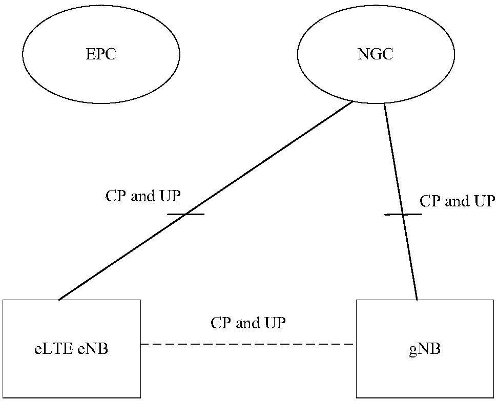
[0127] Please refer to Figure 5 , the UE is configured in an inactive state in the NR network, and the UE AScontext corresponding to the NR network is stored. Subsequently, the UE moves from NR to eLTE. Assuming that the eLTE eNB and NRgNB belong to the same paging area, including the RAN paging area, the UE does not need to update the paging area after entering the eLTE eNB, and does not need to trigger UL transmission. The inactive state of the NR network corresponds to the eLTE system. It is assumed to be the light RRC connection of the RRC connection state (it can also be other names, such as the inactive state. In this mode, the UE and the RAN side air interface are disconnected, but the UE and the RAN side node Each stores the AS context of the UE).

[0128] Step 0: In...

Embodiment 2

[0150] Embodiment 2: After a terminal in the RRC_INACTIVE state (that is, inactive state) of the NR network enters the LTE network from the NR network, UE AS context mapping is performed immediately.

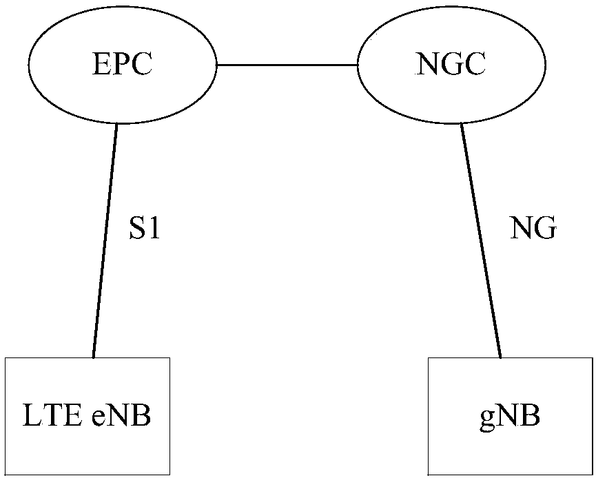
[0151] In the NR network, the UE is configured in an inactive state, and the corresponding UE AS context is stored. Subsequently, the UE moves from NR to LTE. Such as image 3 , since LTE and NR do not belong to the same core network, after UE enters LTE, it needs to perform corresponding TAU (Tracking Area Update (TAU)) update.

[0152] Step 0: In the NR network, the UE enters the inactive state, obtains the allocated UE ID in the inactive state, and stores the corresponding NR network UE AS context. The NR network UE AS context includes at least the following parts:

[0153] 1) RRC configuration before entering the inactive state;

[0154] 2) The security context before entering the inactive state;

[0155] 3) PDCP status, including ROHC status;

[0156] 4) The parameter...

Embodiment 3

[0161] Embodiment 3: After a terminal in the RRC_INACTIVE state (that is, inactive state) of the NR network enters the eLTE network from the NR network, it only performs a state change (subsequent UL does not need to be sent).

[0162] In the NR network, the UE is configured in an inactive state, and the corresponding NR network UE AS context is stored. After the UE moves from NR to eLTE, assuming that the eLTE eNB and NR gNB belong to the same paging area, including the RAN paging area, the UE does not need to update the paging area after entering the eLTE eNB, and does not need to trigger UL transmission. The NR inactive state corresponds to the eLTE system, which is assumed to be a light RRC connection in the RRC connection state.

[0163] Step 0: In the NR network, the UE enters the inactive state, obtains the allocated UE ID in the inactive state, and stores the corresponding NR network UE AS context. The NR network U E AS context includes at least the following paramete...


PUM


Abstract

The invention discloses a cross-RAT terminal state determination method and a terminal, so as to solve the problem of mobility between RATs. The method comprises steps: when a terminal in an inactivestate in a first network system is switched to a second network system different from the first network system from the first network system, the terminal adjusts the current state from the inactive state to a target inactive state corresponding to the second network system; and when a preset condition is met, during a process during which the current state of the terminal is in the target inactive state, the stored source AS context information corresponding to the first network system and source terminal identity information are mapped.

Description

technical field [0001] The present invention relates to the field of communication technology, in particular to a cross-RAT terminal state determination method and a terminal. Background technique [0002] 1. Interface introduction in NextGen network architecture [0003] Such as figure 1 As shown, it is the interface in the NextGen network architecture, where NG2 is the control plane interface between the RAN and the core network; NG3 is the user plane interface between the RAN and the core network; gNB is the base station in the New RAT (NR) system. [0004] 2. Introduction to the cross-RAT network architecture of NR and eLTE / LTE [0005] figure 2 An architecture in which both the NR base station gNB and the eLTE base station eLTE eNB are connected to the 5G core network NGC (NextGen Core); image 3 The NR base station gNB is connected to the 5G core network NGC, while the LTE base station LTE eNB is connected to the 4G core network EPC (Evolved Packet Core) architect...

Claims


Application Information

Patent Timeline
IPC IPC(8): H04W36/00H04W36/14
Inventor 傅婧梁靖张元
Owner DATANG MOBILE COMM EQUIP CO LTD
Why Eureka
Try Eureka