
Deformable kitchen ventilator

A range hood and oil fume technology, applied in the field of deformable range hoods, can solve the problems of wasting gas, easy to touch heads, poor combination, etc., and achieve the effects of improving practical effects, avoiding bumps, and improving smoking effect

Pending Publication Date: 2018-07-13
傅学文
View PDF0 Cites 1 Cited by
  • Summary
  • Abstract
  • Description
  • Claims
  • Application Information

AI Technical Summary

Problems solved by technology

The tower suction type (T-type) can be integrated with the cabinet, with a strong sense of fashion and an elegant and simple appearance, but it is easy to bump into each other, and the smoking effect is not good
The side-suction smoking effect is better, and it is not easy to combine with home decoration cabinets. When the pot is too large, there is no place to put it
If the integrated stove is too close to the stove head, the flame will deviate, wasting gas, and when the pot is too large, there is no place to place it
In the prior art, steam washing, hot water washing, and electric heating washing (there is a potential safety hazard due to line aging) are all based on the length of time to determine whether cleaning is required, all of which are passive cleaning
In this field, the fan suction ports of range hoods are all in the center. Although it can take care of the two cooking surfaces, the suction will drop a lot. Increasing the suction is just to increase the power, which is a waste of resources and money. At the same time, it also increases the noise

Method used


Image

  • Deformable kitchen ventilator
  • Deformable kitchen ventilator

Examples


Embodiment 1

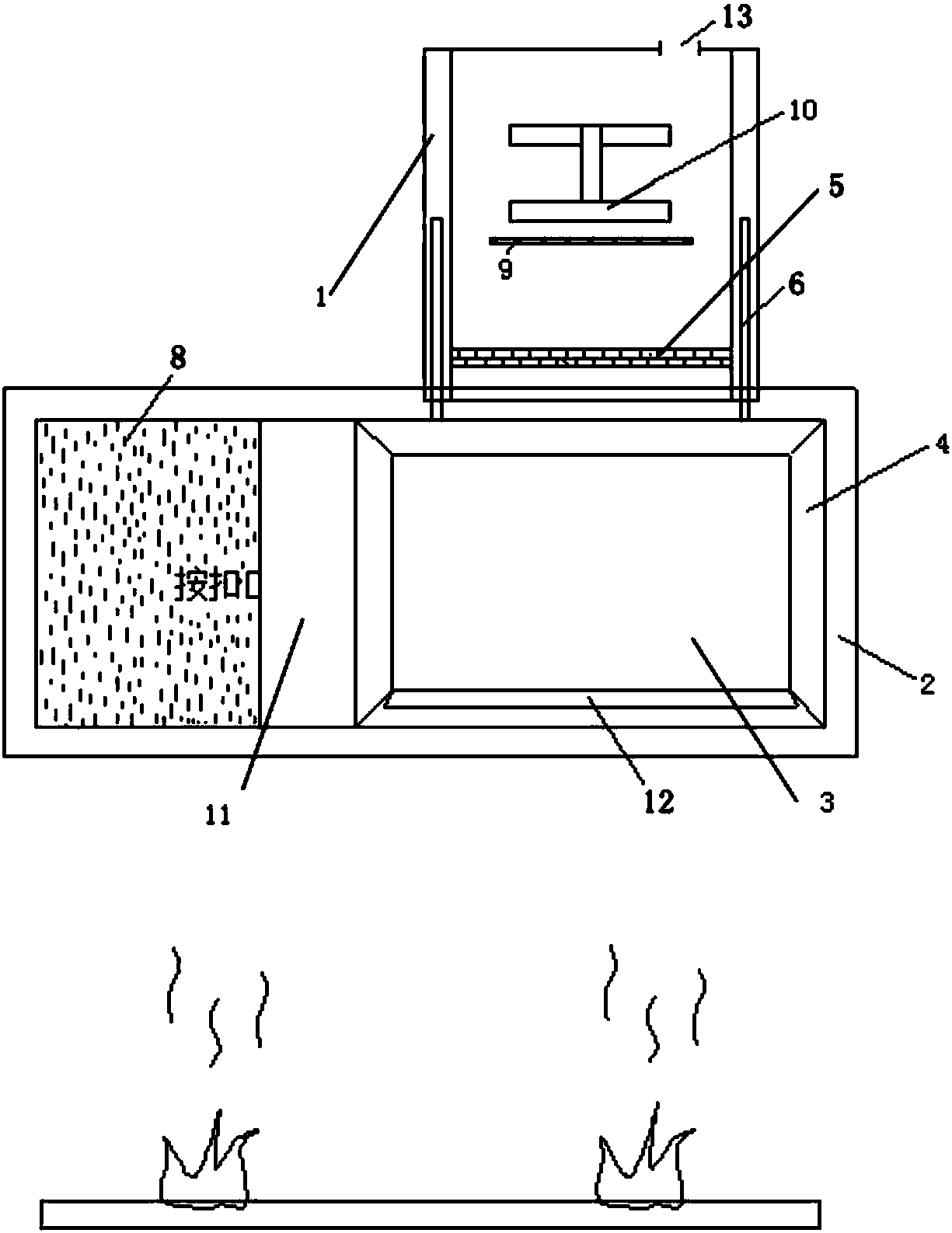
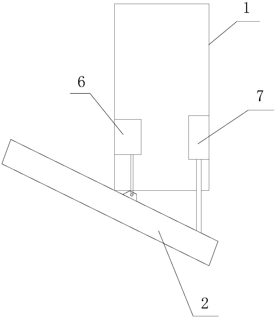
[0025] A deformable range hood is characterized in that it includes a smoke collection hood 2 arranged above the stove, a smoke exhaust part arranged on the top of the smoke collection hood 2, and is used to connect the smoke collection hood 2 and the smoke exhaust The connection part of the part and the control part for controlling the operation of the equipment;

[0026] A soot area and a steam area are arranged inside the fume collecting hood 2, and a heat insulation board 11 is arranged between the soot area and the steam area, and a steam inlet grid 8 is arranged on the top of the soot area, and the inside of the soot area A condensation plate 3 is provided, and a smoke guide plate 4 is provided on the side wall of the oil fume area, and a smoke exhaust passage communicated with the smoke exhaust part is between the smoke guide plate 4 and the condensation plate 3;

[0027] The smoke exhaust part includes a smoke exhaust housing 1 with a hollow structure, the smoke exhaus...


PUM


Abstract

The invention discloses a deformable kitchen ventilator. The deformable kitchen ventilator comprises a fume collecting hood, a fume exhausting part, a connecting part and a control part. A cooking fume area, a steam area and a thermal baffle are arranged inside the fume collecting hood. A steam inlet grating is arranged at the cooking fume area. A condensation plate is arranged inside the cookingfume area. A fume guide plate is arranged on the side wall of the cooking fume area. The fume exhausting part comprises a fume exhausting shell. The fume exhausting shell is provided with a fume exhausting port and a steam outlet. A fume exhausting turbine is arranged inside the fume exhausting shell. The steam inlet grating communicates with the steam outlet. The connecting part comprises liftingracks with telescopic structures. The deformable kitchen ventilator further comprises a rotating part with a telescopic structure. The control part comprises a shift knob and a spin button which arearranged on the fume collecting hood. According to the deformable kitchen ventilator provided by the invention, the steam area and the cooking fume area align a stewing stove and a frying stove correspondingly, and the fume exhausting effect is improved; the fume collecting hood can be lifted up and down and rotated through the lifting racks and the rotating part, and the head bumping probabilityof operators is avoided; and meanwhile, the angle of the fume collecting hood of the kitchen ventilator can be changed and the practical effect is greatly improved.

Description

technical field [0001] The invention relates to the field of range hood equipment, in particular to a deformable range hood. Background technique [0002] Due to the different styles of range hoods, the advantages are also different. There are also many disadvantages. Hoods with oil screens are more difficult to clean grease, and large air volume and suction force will cause loud noise, high cost, and high energy consumption. Among them, the Fangtai range hood only achieves the lifting and lowering of the condensing plate to open the size of the suction port. The tower suction type (T type) can be integrated with the cabinet, with a strong sense of fashion and an elegant and simple appearance, but it is easy to bump into each other, and the smoking effect is not good. The side-suction type has a better smoking effect, and it is not easy to combine with home decoration cabinets. When the pot is too large, there is no place to put it. If the integrated stove is too close to...

Claims


Application Information

Patent Timeline
IPC IPC(8): F24C15/20
CPCF24C15/20F24C15/2085F24C15/2092
Inventor 傅学文
Owner 傅学文
Learn More