Control method of refrigerator

A control method and refrigerator technology, which are applied to household refrigerators, refrigerators, refrigeration components, etc., can solve problems such as temperature rise in storage rooms, storage of unfavorable items, and refrigerators can no longer perform refrigeration and air supply, and achieve good utilization, Good defrosting effect

Pending Publication Date: 2018-07-13
HAIER SMART HOME CO LTD
View PDF5 Cites 0 Cited by
  • Summary
  • Abstract
  • Description
  • Claims
  • Application Information

AI Technical Summary

Problems solved by technology

[0002] In the prior art, due to the circulation of the refrigerant, during the cooling process of the heat exchanger of the air-cooled refrigerator, frost will definitely form on the heat exchanger, and after the frost forms on the heat exchanger, it will cause problems such as energy consumption
At present, the defrosting is usuall

Method used


Image

  • Control method of refrigerator
  • Control method of refrigerator
  • Control method of refrigerator

Examples


Example Embodiment

[0044] Implementation mode one:

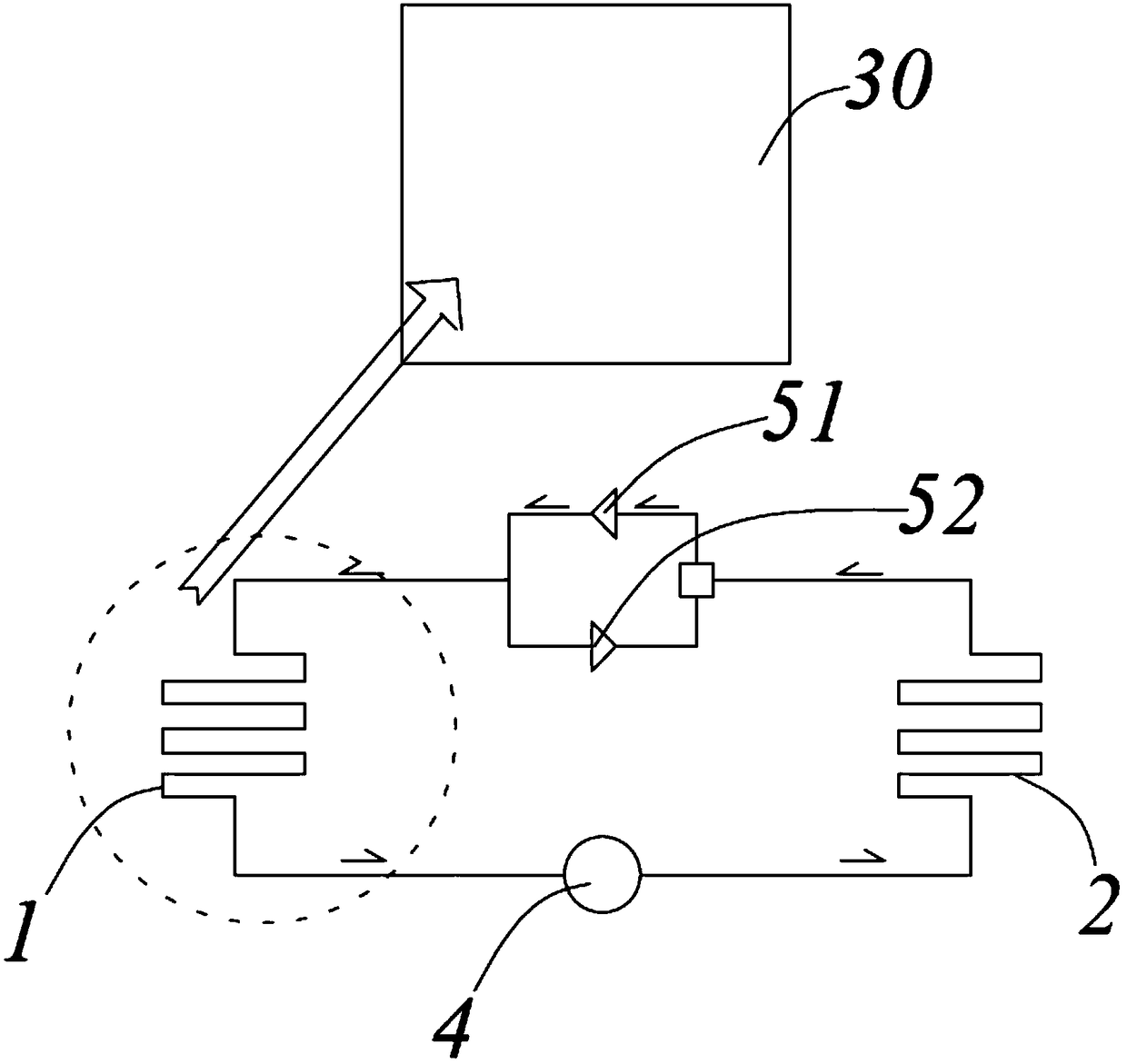
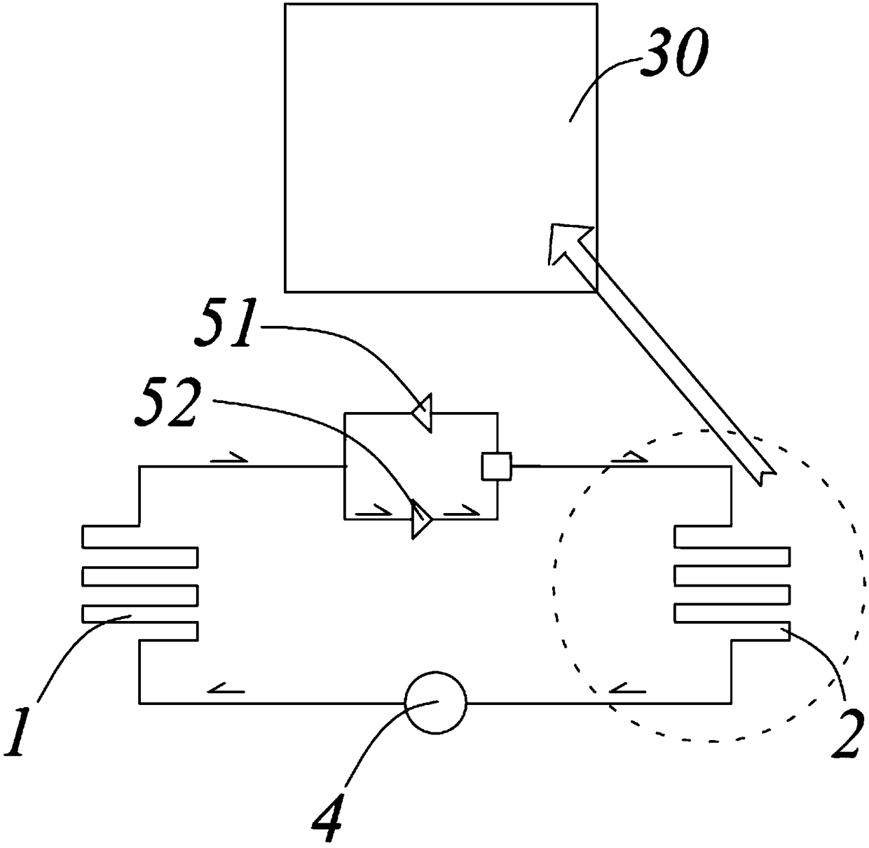
[0045] Such as Figure 1 to Figure 2 As shown, the throttling element includes two first one-way valves 51 and a second one-way valve 52 that are connected in parallel and facing opposite directions. The check valve only allows refrigerant to flow in one direction. The compressor 4 is a bidirectional compressor 4 that allows the refrigerant to flow in a forward or reverse direction, that is, the compressor 4 can control the refrigerant to flow in two different directions. The compressor 4 and the throttle element are respectively connected to the two ends of the first heat exchanger 1 to form a refrigerant flow circuit. When the compressor 4 causes the refrigerant to flow in the forward direction, the refrigerant passes through the first check valve 51, and when the compressor 4 causes the refrigerant to flow in the reverse direction, the refrigerant passes through the second check valve 52, so that the cooling The circulation of the agent form...

Example Embodiment

[0051] Implementation mode two:

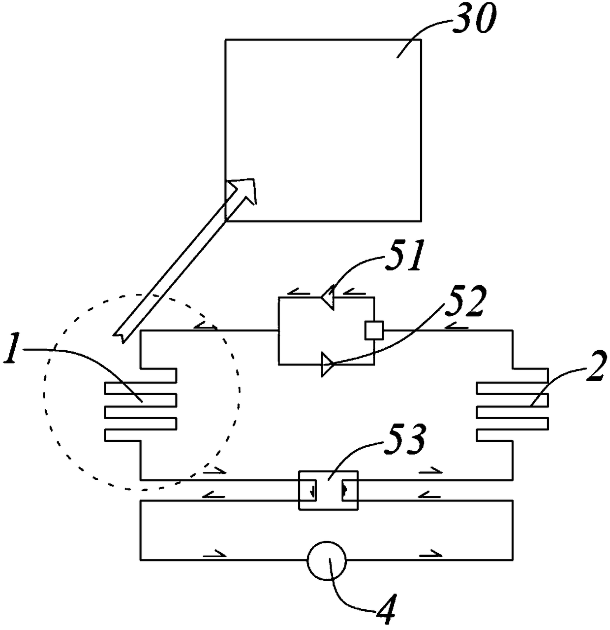
[0052] Such as Figure 3 to Figure 4 As shown, the throttling element includes two parallel-oriented first one-way valves 51 and second one-way valves 52 facing in opposite directions, and the compressor 4 is a one-way compressor 4 that allows only one-way flow of refrigerant. . In this embodiment, since the one-way compressor 4 is used, the temperature control system in this embodiment further includes a four-way valve 53. The four-way valve 53 includes an inlet and an outlet respectively connected to both ends of the compressor 4, and two other communication ports respectively connected to the first heat exchanger 1 and the second heat exchanger 2. In this embodiment, the inlet of the four-way valve 53 refers to the end where the refrigerant flows out, and the outlet of the four-way valve 53 refers to the end where the refrigerant flows in.

[0053] When the inlet of the four-way valve 53 is connected to the first heat exchanger 1 and the outle...

Example Embodiment

[0059] Implementation mode three:

[0060] Such as Figure 5 to Figure 6 As shown, the throttling element is a two-way valve 54, the compressor 4 is a two-way compressor 4 that allows refrigerant to flow in the forward or reverse direction, and the compressor 4 and the two-way valve 54 are respectively connected to the first converter Both ends of the heat exchanger 1; so that when the compressor 4 makes the refrigerant flow forward or reverse, the refrigerant can pass through the two-way valve 54.

[0061] In the third embodiment, the two-way compressor 4 and the two-way valve 54 that allow the refrigerant to flow in both directions are used, so that when the compressor 4 controls the refrigerant to change the flow direction, the two-way valve 54 can allow the refrigerant to pass.

[0062] In the third embodiment, the “controlling the forward flow of refrigerant and flowing from the second heat exchanger to the first heat exchanger” includes:

[0063] Control the compressor to run fo...


PUM


Abstract

The invention discloses a control method of a refrigerator. A temperature control system comprises a compressor, a first heat exchanger, a throttling element and a second heat exchanger, wherein the first heat exchanger is arranged close to a first chamber; the second heat exchanger is arranged close to a second chamber; the refrigerator comprises two air channels, a first air door and a second air door; the first chamber communicates with a third chamber through one of the two air channels, and the second chamber communicates with the third chamber through another air channel; the two air channels are correspondingly controlled to be opened and closed through the first air door and the second air door. The control method comprises the steps of starting the compressor; controlling a refrigerant to flow in forward direction and flow from the second heat exchanger to the first heat exchanger; refrigerating through the first chamber; heating through the second chamber; recording the length of time that the refrigerant flows in the forward direction as T1; controlling the refrigerant to flow in reverse direction and flow from the first heat exchanger to the second heat exchanger; heating through the first chamber; refrigerating through the second chamber; recording the length of time that the refrigerant flows in the reverse direction as T2; detecting the real-time temperature theta of the third chamber; and determining the difference between the real-time temperature theta and threshold temperature T0.

Description

technical field [0001] The present application relates to the field of home appliances, in particular to a method for controlling a refrigerator. Background technique [0002] In the prior art, due to the circulation of the refrigerant, during the cooling process of the heat exchanger of the air-cooled refrigerator, frost will definitely form on the heat exchanger. After the frost forms on the heat exchanger, problems such as energy consumption will be caused. At present, the defrosting is usually carried out by heating the heating wire under certain conditions to defrost the frosting. However, the defrosting device and the refrigerator are usually unable to refrigerate and supply air, which causes the temperature of the storage room in the refrigerator to rise again, thus preventing Conducive to the preservation of items. Therefore must design a kind of control method of refrigerator, solve the problem of defrosting, can keep the temperature constant refrigeration in the r...

Claims


Application Information

Patent Timeline
IPC IPC(8): F25D11/02F25D19/00F25D21/06F25D29/00F25B13/00F25B41/06F25B41/38
CPCF25B13/00F25D11/02F25D19/00F25D21/06F25D29/005F25D2700/12F25B2313/02792F25B41/30Y02B40/00
Inventor 张奎吴乔晔
Owner HAIER SMART HOME CO LTD
Why Eureka
Try Eureka