Supercharge Your Innovation With Domain-Expert AI Agents!

Active clamp converter and its control method

A control method and clamping technology, which is applied in the field of converters, can solve the problem of high switching loss and achieve the effect of reducing switching loss and voltage difference

Active Publication Date: 2019-07-12
ACBEL POLYTECH INC
View PDF7 Cites 0 Cited by
  • Summary
  • Abstract
  • Description
  • Claims
  • Application Information

AI Technical Summary

Problems solved by technology

[0012] However, the current level of the excitation current of the general active clamp converter will change with the state of the load 130. Generally speaking, when the load 130 is higher, the current level of the excitation current at the primary side of the active clamp converter will be higher, so when the state of the load 130 exceeds a first critical value, when the current in the oscillation circuit of the primary side is oscillating back and forth, the current minimum value of the valley will be due to the excitation current of the primary side of the active clamp converter The current level of the current level is pulled up to exceed 0 ampere, that is, when the state of the load 130 exceeds a first critical value, no reverse current will be generated, so the body diode (body diode) of the main switching element Q1 does not It will conduct forward, so the voltage difference between the two ends of the main switching element Q1 will not decrease, resulting in too high switching loss when the main switching element Q1 switches

Method used


Image

  • Active clamp converter and its control method
  • Active clamp converter and its control method
  • Active clamp converter and its control method

Examples


Embodiment Construction

[0065] The technical means adopted by the present invention to achieve the intended purpose are further described below in conjunction with the drawings and preferred embodiments of the present invention.

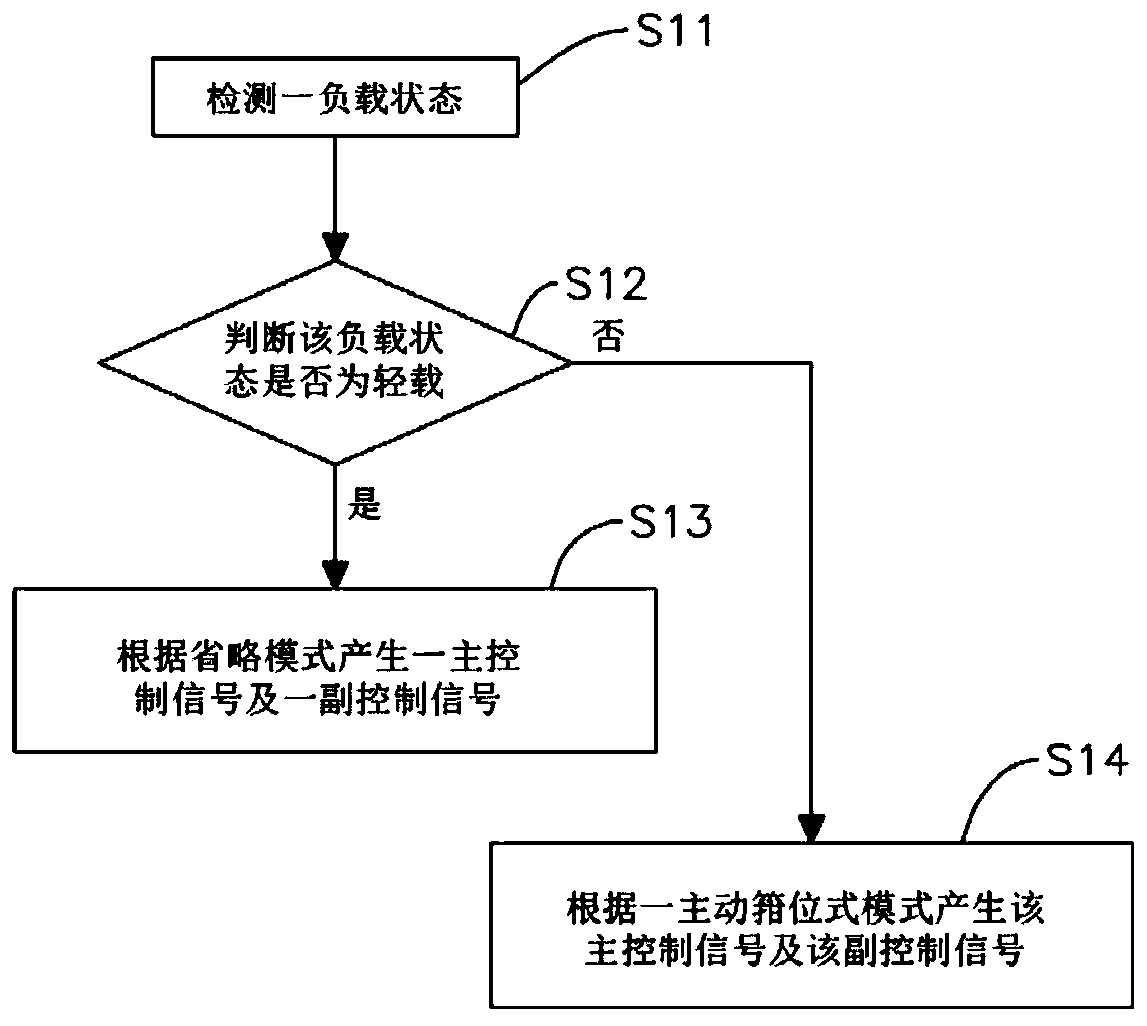
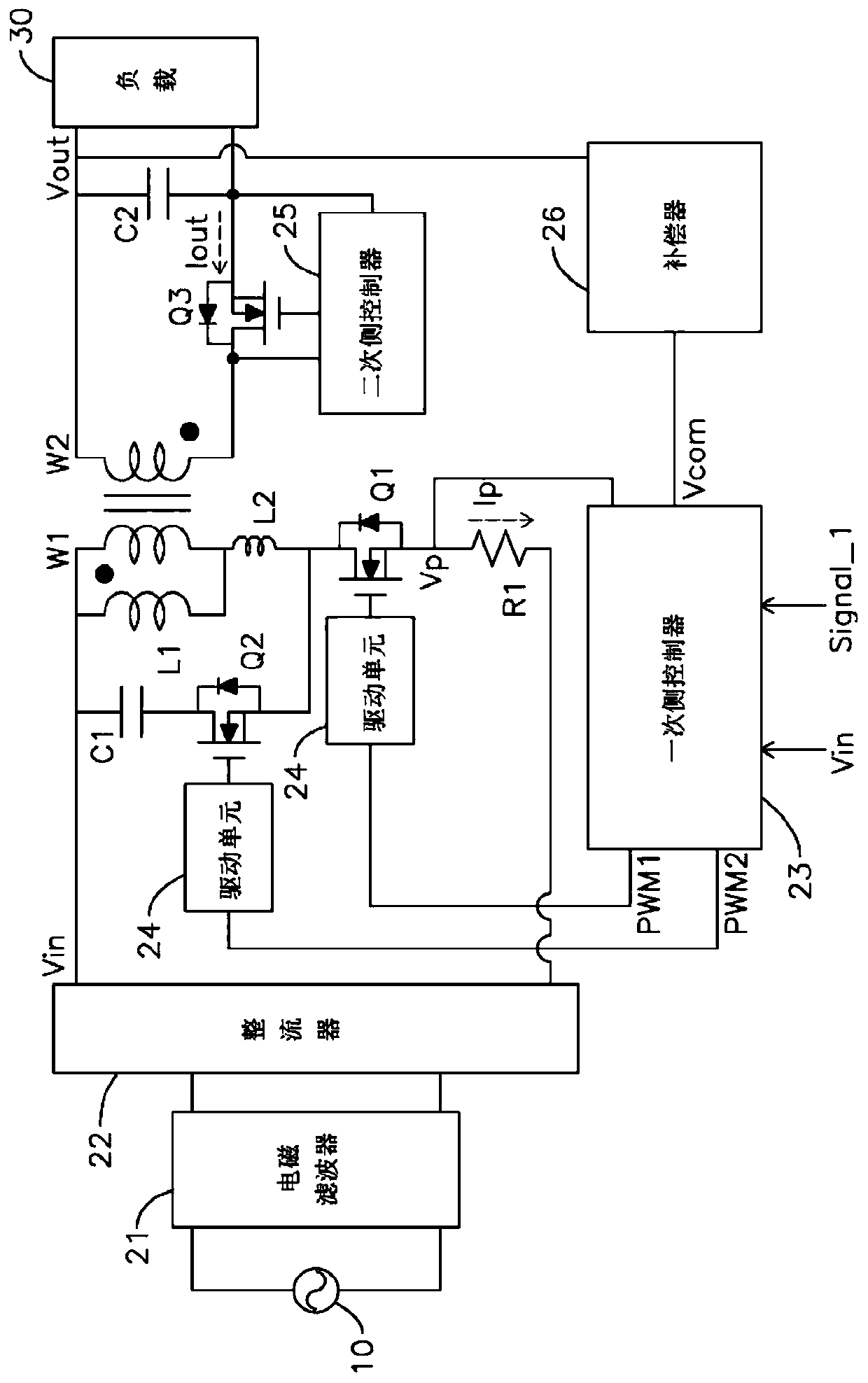
[0066] see figure 1 As shown, the present invention is an active clamp converter and its control method. The control method of the active clamp converter controls a main switching element and a secondary switching element on the primary side of an active clamp converter, And contains the following steps:

[0067] Detect a load state (S11);

[0068] Judging whether the load state is light load (S12);

[0069] When the load state is light load, a main control signal and a sub-control signal are generated according to a skipping mode (S13); wherein the main control signal controls whether the main switching element is turned on or not, and the sub-control signal The signal controls whether the auxiliary switching element is turned on or not; wherein the omission mode is to...


PUM


Abstract

The present invention is an active clamp converter and its control method, including the following steps: detecting a load state, when the load state is light load, controlling the switching frequency of a main switching element according to an omission mode, and when the load When the state is not light load, the switching frequency of the main switching element is controlled according to an active clamp mode. In the omission mode, the switching frequency of the main switching element decreases as the load decreases, so as to meet the energy efficiency condition under light load and provide a power saving mode (power saving) function. In the active clamping mode, the main switching element is controlled to be turned on when reverse current is generated, thereby reducing the switching loss when the main switching element switches.

Description

technical field [0001] The invention is a converter, especially an active clamp converter and its control method. Background technique [0002] see Figure 13 Middle (a)~(f) and Figure 14 As shown, the waveform diagram and equivalent circuit diagram of the control signal of the general active clamp converter, the general active clamp converter has a primary side and a secondary side, the primary side is electrically connected to an AC power source 110, And includes an electromagnetic filter 121, a rectifier 122, a main switching element Q1, a secondary switching element Q2, a magnetizing inductance L1, a primary side leakage inductance L2, a primary side capacitor C1 and a primary side coil W1 . [0003] The electromagnetic filter 121 is electrically connected between the AC power source 110 and the rectifier 122 to isolate the electromagnetic interference in the AC power source 110. The rectifier 122 receives the AC power source 110 and outputs it after rectification, an...

Claims


Application Information

Patent Timeline
Patent Type & Authority Patents(China)
IPC IPC(8): H02M3/335
CPCH02M3/33576H02M1/0054Y02B70/10
Inventor 叶家安庄书玮
Owner ACBEL POLYTECH INC
Features
  • R&D
  • Intellectual Property
  • Life Sciences
  • Materials
  • Tech Scout
  • Unparalleled Data Quality
  • Higher Quality Content
  • 60% Fewer Hallucinations
Learn More