
A method for measuring cell signal power

A signal power and power technology, applied in the field of communication, can solve the problems of timing deviation, frequency deviation, difficulty in obtaining measurement results, etc., to achieve the effect of improving measurement accuracy and reducing implementation costs

Active Publication Date: 2019-09-24
罗锦超
View PDF3 Cites 0 Cited by
  • Summary
  • Abstract
  • Description
  • Claims
  • Application Information

AI Technical Summary

Problems solved by technology

The problem with existing cell signal power measurement solutions is that it is difficult to obtain accurate measurement results due to the influence of timing deviation and frequency deviation in the scenario of synchronization deviation

Method used


Image

  • A method for measuring cell signal power
  • A method for measuring cell signal power
  • A method for measuring cell signal power

Examples


specific Embodiment 1

[0047] This embodiment is a preferred implementation of the cell signal power measurement method of the present invention.

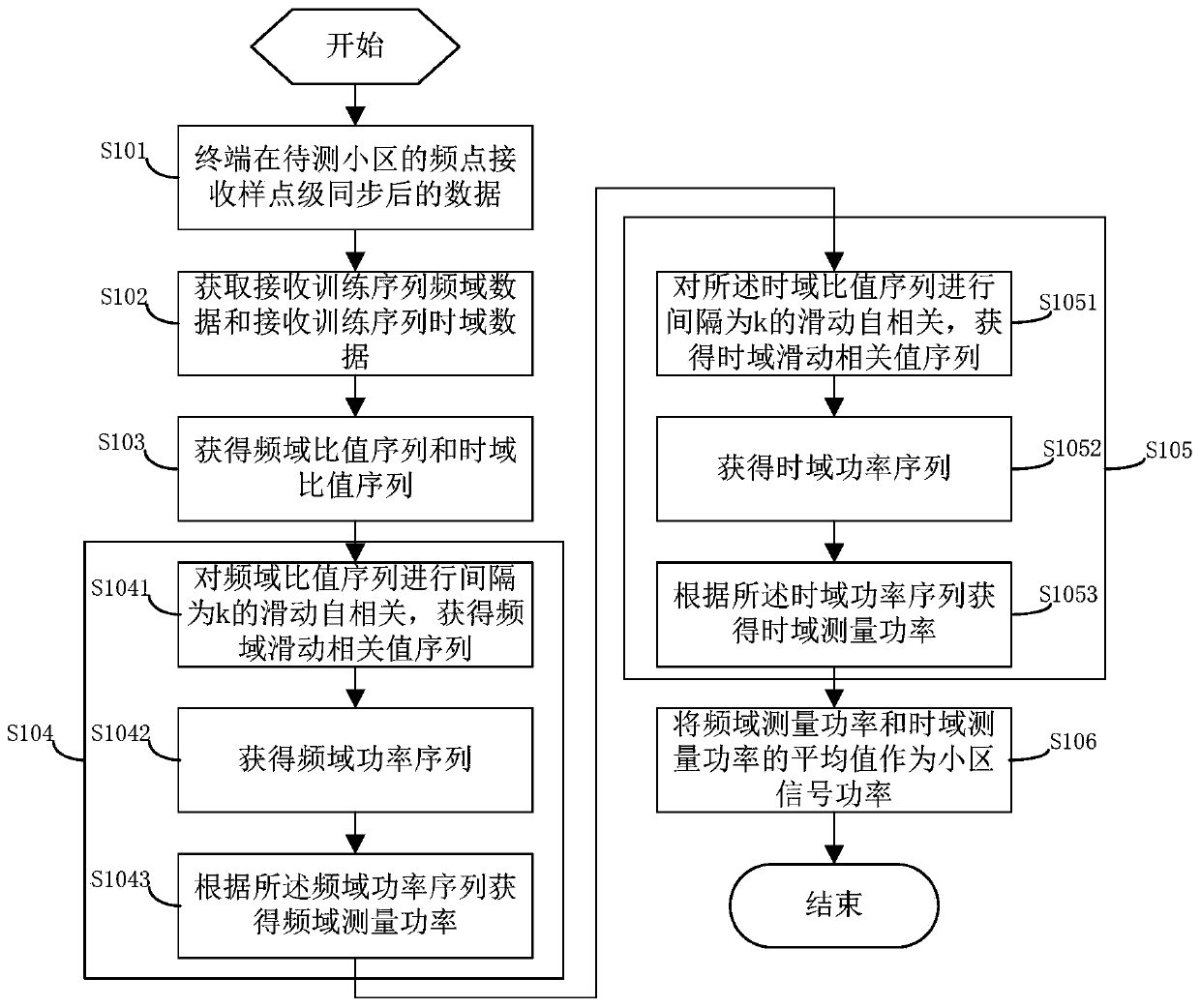
[0048] See figure 1 ,Such as figure 1 As shown, the cell signal power measurement method in this embodiment includes:

[0049] S101: The terminal receives sample-level synchronized data at the frequency point of the cell to be tested;

[0050] Determine the frequency point of the cell to be tested according to the measurement task. After completing the sample-level synchronization, start receiving data from the beginning of the midamble in the P-CCPCH, and receive a total of 128 samples to obtain the received data;

[0051] Wherein, the sample-level synchronization can adopt various sample-level synchronization methods in the prior art, and the present invention has no specific limitation on this;

[0052] S102. Obtain frequency-domain data of the received training sequence and time-domain data of the received training sequence.

[0053] Perform co-frequency interf...

specific Embodiment 2

[0090] This embodiment is another preferred implementation of the cell signal power measurement method of the present invention.

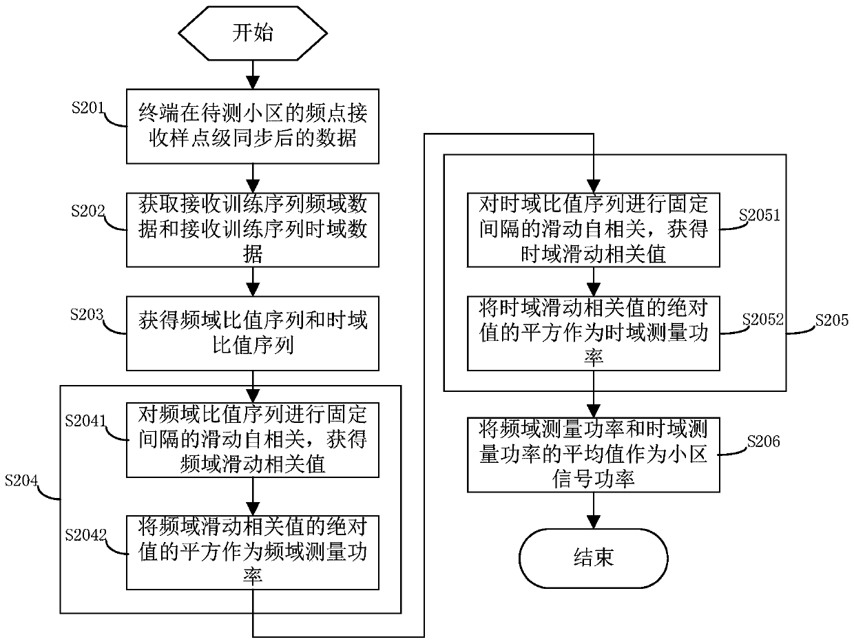
[0091] See figure 2 ,Such as figure 2 As shown, the measurement method of this embodiment includes:

[0092] S201: The terminal receives sample-level synchronized data at the frequency point of the cell to be tested;

[0093] Determine the frequency point of the cell to be tested according to the measurement task. After completing the sample-level synchronization, start receiving data from the beginning of the midamble in the P-CCPCH, and receive a total of 128 samples to obtain the received data;

[0094] Wherein, the sample-level synchronization can adopt various sample-level synchronization methods in the prior art, and the present invention has no specific limitation on this;

[0095] S202: Obtain frequency-domain data of the receiving training sequence and time-domain data of the receiving training sequence;

[0096] Perform co-frequency interference...


PUM


Abstract

The invention discloses a cell signal power measurement method. The method comprises the following steps: receiving sample point-level synchronized data at a frequency point of a to-be-measured cell by a terminal; acquiring receiving training sequence frequency domain data and receiving training sequence time domain data from the received data; dividing local training sequence frequency domain data by the receiving training sequence frequency domain data to obtain a frequency domain ratio sequence; dividing the local training sequence time domain data by using the receiving training sequence time domain data to obtain a time domain ratio sequence; performing slipping autocorrelation on the frequency domain ratio sequence to obtain the frequency domain measurement power; performing slippingautocorrelation on the time domain ratio sequence to obtain time domain measurement power; and taking the greater value in the frequency domain measurement power and the time domain measurement poweras the cell signal power. Through the technical scheme disclosed by the invention, the influence on the cell signal power measurement by the timing deviation and frequency deviation can be effectively reduced, and the measurement precision is improved.

Description

Technical field [0001] The present invention relates to the field of communication technology, and in particular to a method for measuring cell signal power in a cellular wireless communication system. Background technique [0002] In a mobile communication system, mobile terminals need to measure the cell signal power when performing cell selection, cell reselection, cell handover, and other radio resource management activities to select a cell that meets the power condition to camp on. [0003] In different communication systems, the measurement objects and names are different, but there are a large number of measurement objects that essentially only use the signal power of the cell to be tested, and do not include noise and interference. Such as time division synchronous code division multiple access (abbreviation, TD-SCDMA) system, wideband code division multiple access (abbreviation, WCDMA) system received signal code power (abbreviation, RSCP), and long-term evolution (abbrev...

Claims


Application Information

Patent Timeline
Patent Type & Authority Patents(China)
IPC IPC(8): H04B17/327
Inventor 蒋文豪李铮欧阳卫华
Owner 罗锦超
Learn More