
Cooperative receiving method and system based on air interface information fusion

A technology of cooperative reception and air interface, applied in the field of wireless communication, which can solve the problems of high bit error rate, prolonged interaction time, and poor network scalability.

Active Publication Date: 2020-10-20
ZHEJIANG UNIV
View PDF7 Cites 2 Cited by
  • Summary
  • Abstract
  • Description
  • Claims
  • Application Information

AI Technical Summary

Problems solved by technology

In this method, when the number of receivers is large, the calculation waiting delay will be greatly increased, which will cause the problem of poor network scalability.
[0007] It can be seen that the current cooperative reception technology has defects such as high bit error rate, prolonged interaction time, and poor network scalability.

Method used


Image

  • Cooperative receiving method and system based on air interface information fusion
  • Cooperative receiving method and system based on air interface information fusion
  • Cooperative receiving method and system based on air interface information fusion

Examples


Embodiment 1

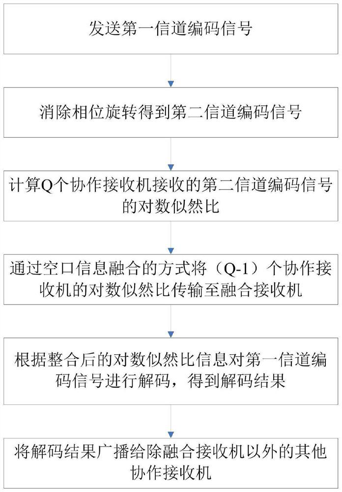
[0064] figure 1 It is a method flow chart of a cooperative receiving method based on air interface information fusion provided by the present invention. see figure 1 , a cooperative receiving method based on air interface information fusion provided by the present invention includes:

[0065] Step 1: Send the first channel coded signal to N cooperative receivers (receiving clusters) at the same time.

[0066] Step 2: Eliminate the phase rotation of the channel to the first channel-coded signal to obtain a second channel-coded signal. The specific methods include:

[0067] sending pilot signals to the N cooperative receivers;

[0068] Estimate the channel by using the least square method or the method of minimizing the mean square error according to the pilot signal, and calculate the signal-to-noise ratio of the pilot signal according to the channel estimation result;

[0069] sending a first channel coded signal to the N cooperative receivers;

[0070] The phase rotation...

Embodiment 2

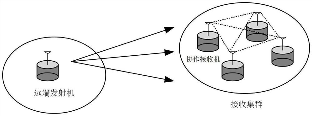
[0099] figure 2 A system structure diagram of a cooperative receiving system based on air interface information fusion provided in Embodiment 2 of the present invention, image 3 A diagram of the relationship between the transmitter and the cooperative receiver in the cooperative receiving system based on air interface information fusion provided by Embodiment 2 of the present invention. see figure 2 and image 3 , a cooperative receiving system based on air interface information fusion provided by the present invention, comprising:

[0100] Transmitter, cooperative receiver, log likelihood ratio calculation module, air interface information fusion transmission module, information integration module, decoding module, propagation module;

[0101] There are N cooperative receivers, where N is a set constant;

[0102] The transmitter is used to simultaneously send the first channel coded signal to N cooperative receivers;

[0103] The cooperative receiver is used to elimin...


PUM


Abstract

The invention relates to a cooperative receiving method and a system based on air interface information fusion, and the method comprises the steps: obtaining a second channel coding signal through eliminating the phase rotation of a channel for a first channel coding signal; selecting a cooperative receiver within a set signal-to-noise ratio range of the second channel coded signal, controlling the cooperative receiver to calculate a log-likelihood ratio, and transmitting log-likelihood ratio information of (Q-1) cooperative receivers to the remaining cooperative receivers in an air interfaceinformation fusion mode; and controlling the remaining cooperative receivers to integrate the log-likelihood ratio information of the Q cooperative receivers, and decoding the first channel coded signal according to the integrated log-likelihood ratio information to obtain a decoding result. According to the invention, the cooperative decoding time delay can be greatly reduced, the bit error rateis reduced, more receivers are supported for cooperation, and the expandability of the system is improved.

Description

technical field [0001] The present invention relates to the technical field of wireless communication, in particular to a cooperative reception method and system based on air interface information fusion. Background technique [0002] In recent years, cooperative communication technology has become one of the hot research areas of wireless communication. Cooperative reception technology combines the received signals of multiple receivers in the wireless network to form a virtual antenna array to increase diversity and power gain, thereby increasing the possibility of successfully decoding noisy transmissions, and improving wireless network capacity and bit error rate performance potential. Cooperative reception may also result in increased communication range, increased data rate and / or reduced transmit power. [0003] Existing cooperative receiving technologies can be roughly divided into the following categories: [0004] a. Each receiver broadcasts its received signal ...

Claims


Application Information

Patent Timeline
Patent Type & Authority Applications(China)
IPC IPC(8): H04L1/00H04L27/26
CPCH04L1/0009H04L27/2695
Inventor 刘安刘冠颖赵民建
Owner ZHEJIANG UNIV
Learn More