Foldable catapult type unmanned aerial vehicle

A technology of unmanned aerial vehicle and folding mechanism, which is applied in the direction of fuselage, aircraft parts, aircraft control, etc. It can solve the problems of taking out and unfolding, multiple disassembly and assembly, inconvenient storage and carrying, etc., so as to enhance combat capability, Wide range of applications, saving storage and loading space

Pending Publication Date: 2018-07-17
王洪涛
View PDF0 Cites 0 Cited by
  • Summary
  • Abstract
  • Description
  • Claims
  • Application Information

AI Technical Summary

Problems solved by technology

However, most of the unmanned aerial vehicles in the prior art have unreasonable structural design. Because the wings cannot be folded, the structure size is large, which is inconvenient to store and carry. The problem of assembly, especially when it is applied in the military field, will bring great inconvenience
In order to overcome this shortcoming, there are also foldable UAVs developed and produced in recent years, most of which are foldable wings. However, this foldable UAV in the prior art has the following problems: although the wings can be Folding, but only when storing the drone to save space, it needs to be taken out and unfolded before use, compared to fixed wing aircraft, its advantage is only to save space when storing
Especially when it is applied in the military field, there are many restrictions, because in military applications, UAVs are often used together with launch vehicles, and take off by catapult to complete the purpose of hitting the target. At present, the existing foldable UAV This requirement cannot be met. Therefore, it is necessary to provide a collapsible catapult UAV that can not only be folded and save loading space, but also be suitable for catapult take-off. application is important

Method used


Image

  • Foldable catapult type unmanned aerial vehicle
  • Foldable catapult type unmanned aerial vehicle
  • Foldable catapult type unmanned aerial vehicle

Examples


Embodiment Construction

[0023] This section will further explain and describe the specific implementations in conjunction with the accompanying drawings. It should be noted that the specific implementations described in this section are only used to explain and illustrate the present invention, and do not constitute limitations to the present invention.

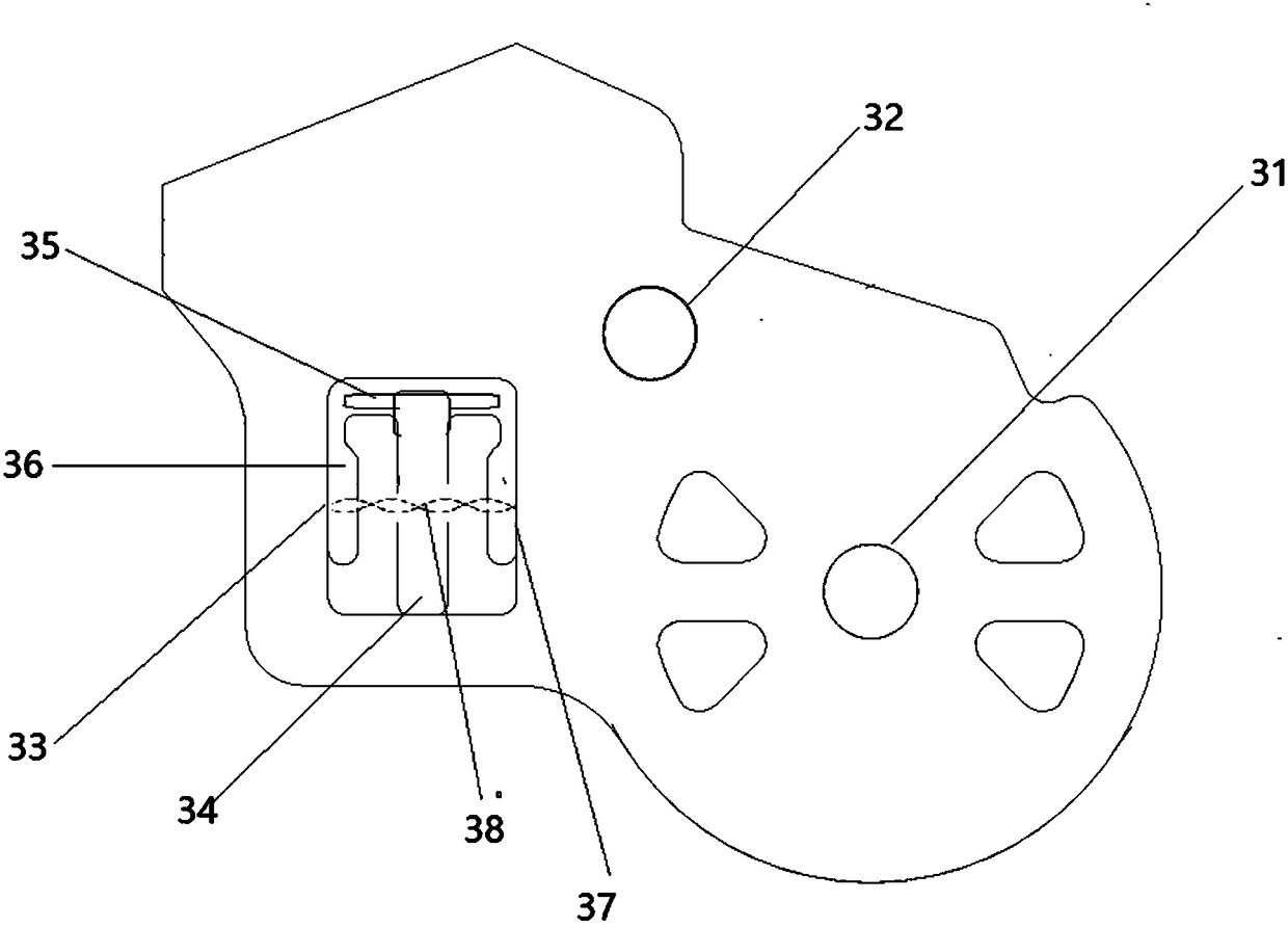
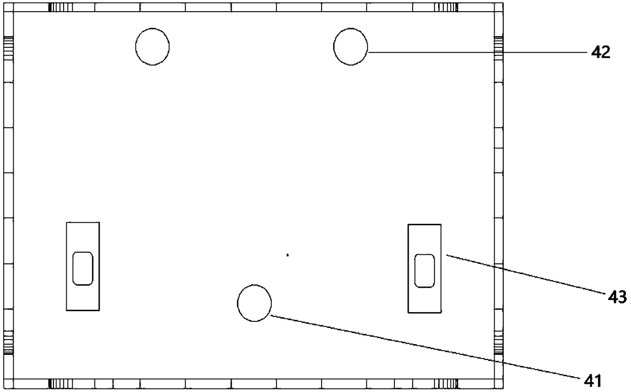
[0024] as attached figure 1 , 2 , 4, a foldable catapult UAV, including a fuselage 1, a wing 2, is characterized in that: it also includes a folding mechanism 3 installed on the wing 2 and a base 4 embedded in the fuselage 1 , the wing 2 is installed on the base 4 of the fuselage 1 through the folding mechanism 3; the drone is a "shi"-shaped drone, and the wings are two main wings. Since there are two symmetrical main wings, the folding mechanism 3 installed on the wings is symmetrically hinged on the positioning shaft 41 of the base 4 through the positioning holes 31 thereon.

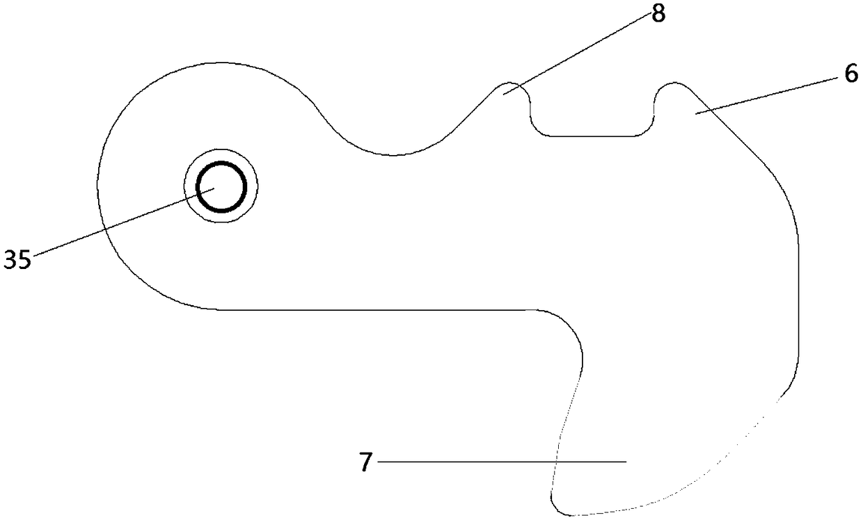
[0025] The folding mechanism 3 is provided with a positioning hole 31...


PUM


Abstract

By designing of a novel folding mechanism and unfolding-locking device on a wing and a fuselage, the invention provides a foldable catapult type unmanned aerial vehicle which can be folded, can save loading space, can be suitable for catapult type takeoff and can be automatically unfolded. The foldable catapult type unmanned aerial vehicle can be applied to cross-shaped and I-shaped unmanned aerial vehicles, and can be applied to other types of unmanned aerial vehicles, such as multi-rotor type, and the wide application range is achieved. The unmanned aerial vehicle can be folded and loaded when not used, so that storage space and loading space are saved. The unmanned aerial vehicle can automatically unfold the wing when the unmanned aerial vehicle takes off, and automatically lock up whenthe wing reaches the full unfolding position, so that the wing is fixed at the required position, and the foldable unmanned aerial vehicle can be applied to the catapult type takeoff. The foldable catapult type unmanned aerial vehicle is exquisite and reasonable in design, easy to load and transport, capable of automatically unfolding during the catapult type takeoff, and capable of filling the blank in the field.

Description

technical field [0001] The invention relates to the field of unmanned aerial vehicles, in particular to a catapult unmanned aerial vehicle with foldable wings. Background technique [0002] UAV is the abbreviation of "unmanned aircraft". In recent years, both research and industrial applications have developed rapidly, and are widely used in military, agriculture, communication, photography and many other fields. However, most of the unmanned aerial vehicles in the prior art have unreasonable structural design. Because the wings cannot be folded, the structure size is large, which is inconvenient to store and carry. The problem of assembly will bring great inconvenience especially when it is applied in the military field. In order to overcome this shortcoming, there are also foldable UAVs developed and produced in recent years, most of which are foldable wings. However, this foldable UAV in the prior art has the following problems: although the wings can be Folding, but on...

Claims


Application Information

Patent Timeline
Patent Type & Authority Applications(China)
IPC IPC(8): B64C1/30B64C1/00B64F1/06
CPCB64C1/30B64C1/00B64F1/06
Inventor 王洪涛
Owner 王洪涛
Why Eureka
Try Eureka