Three-face transpression load-supporting cable beam anchorage structure of cable-stayed bridge concrete box girder

An anchoring technology for concrete box girders and cable girders, applied in the field of bridge structures, can solve problems such as difficulties in concrete construction, conflicts between long cable sleeves and dense steel bars, concrete cracking, etc., to overcome long-term corrosion resistance and poor maintenance accessibility , avoid mass concrete pouring problems, improve the effect of section transition and force

Pending Publication Date: 2018-07-17
CHINA RAILWAY SIYUAN SURVEY & DESIGN GRP +2
View PDF0 Cites 0 Cited by
  • Summary
  • Abstract
  • Description
  • Claims
  • Application Information

AI Technical Summary

Problems solved by technology

[0004] However, there are the following problems in the cable-girder anchorage structure of existing conventional concrete box-girder cable-stayed bridges: 1. Since both sides of the concrete box-girder are designed as a large-volume solid area A, the amount of concrete is relatively large, and the concrete is difficult to vibrate and water The heat of transformation is large; 2. There is a large abrupt change in stiffness between the roof E of the concrete box girder section and the solid area A on both sides, which is prone to large stress concentration and cracks in the concrete; 3. Steel sleeve C It needs to run through the entire concrete large-volume solid area A, and the steel sleeve C will conflict with the dense steel bars in the solid area A and the transverse prestressed tendons of the beam; 4. Most of the stay cables are spatially linear, and the corresponding steel sleeves C is also arranged in a three-dimensional space direction. Since the steel sleeve C is embedded long, it is difficult to locate the steel sleeve C; 5. The stay cable anchorage structure is located in the atmospheric environment at the bottom of the beam, and the accessibility of this position is poor. It is not convenient for daily maintenance, and it is not conducive to the anticorrosion of the anchorage structure of the cable stay; The shear stress of the junction surface F of the beam bottom, the tensile stress of the junction I of the anchorage surface G of the anchor block and the junction of the beam bottom H, and the problem that the crack is large or even exceeds the limit
[0005] To sum up, for the concrete box girder cable-stayed bridge, how to design a cable-beam anchorage structure with reasonable force, reliable force transmission, convenient construction, easy control of construction quality, economical saving, long-term anti-corrosion, and easy maintenance to overcome The existing cable-beam anchorage structure is equipped with large-volume solid areas on both sides, resulting in difficulties in concrete construction, concrete cracks caused by sudden changes in stiffness, conflicts between long cable sleeves and dense steel bars, and difficult positioning of long sleeves. Maintenance and prolonging the service life of the anchorage structure and optimizing the force transmission mechanism of the anchorage structure of the cable beam are one of the key technical issues to be studied and solved in this field.

Method used


Image

  • Three-face transpression load-supporting cable beam anchorage structure of cable-stayed bridge concrete box girder
  • Three-face transpression load-supporting cable beam anchorage structure of cable-stayed bridge concrete box girder
  • Three-face transpression load-supporting cable beam anchorage structure of cable-stayed bridge concrete box girder

Examples


Embodiment Construction

[0030] The specific implementation manners of the present invention will be further described in detail below in conjunction with the accompanying drawings and specific embodiments. The following examples are only used to illustrate the present invention, and are not intended to limit the specific protection scope of the present invention.

[0031] In the description of the present invention, unless otherwise specified, the meaning of "plurality" is two or more; ", "connection" should be understood in a broad sense, for example, it can be a fixed connection, a detachable connection, or an integral connection; it can be a direct connection or an indirect connection through an intermediary. Those of ordinary skill in the art can understand the specific meanings of the above terms in the present invention in specific situations.

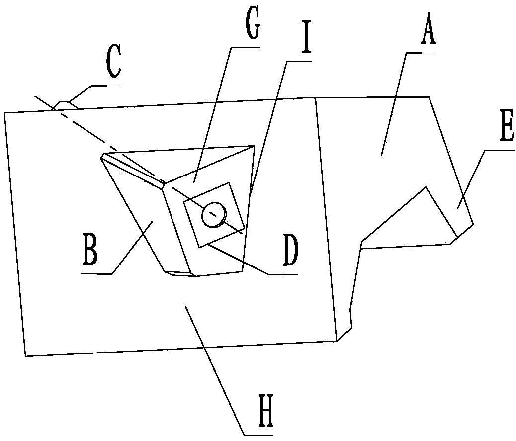
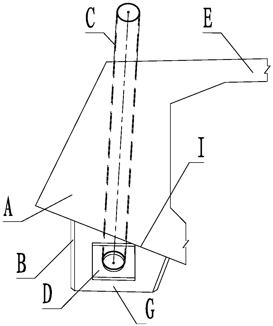
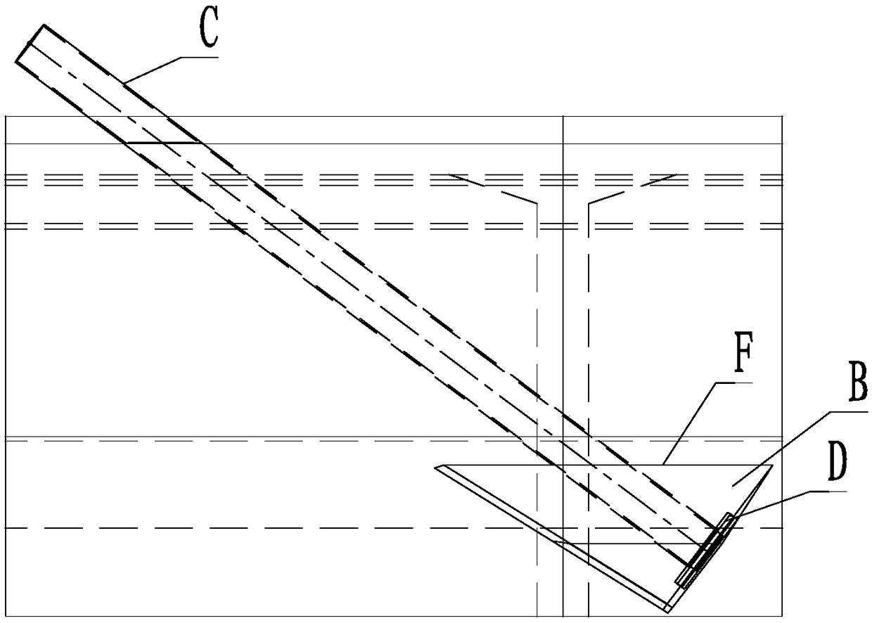
[0032] like Figure 4-7 As shown, a cable-stayed bridge concrete box girder three-sided compression-shear load-bearing cable-beam anchorage structure...


PUM

PropertyMeasurementUnit
Thicknessaaaaaaaaaa
Thicknessaaaaaaaaaa
Lengthaaaaaaaaaa

Abstract

The invention discloses a three-face transpression load-supporting cable beam anchorage structure of a cable-stayed bridge concrete box girder. The three-face transpression load-supporting cable beamanchorage structure of the cable-stayed bridge concrete box girder comprises a box girder composed of a roof plate, a side web plate and a diaphragm plate, and a concrete anchorage block for transmitting cable force to the box girder. The concrete anchorage block is positioned on one side of a back tower in a box girder chamber cavity, that is, is arranged at the intersection of the roof plate, the side web plate and the diaphragm, and the concrete anchorage block is poured into one with the roof plate, the side web plate and the diaphragm plate. A cable sleeve penetrates through the diaphragmplate and the roof plate, the diaphragm plate is of a thickened plate structure with large holes in the middle portion, and the side web plate is of a plate-type structure with the thickness of 45-60cm. A load-transferring mechanism of the cable beam anchorage structure is three-face transpression load-supporting, the load-transferring of the structure is clear and reliable, the cross section transition and the force of the cross section of a main beam are greatly improved, and the problem of the mass concrete pouring of the main beam is avoided; the problems that the long-term effect of corrosion protection and maintenance accessibility are poor in an existing cable beam anchorage structure are overcome; and truncation of steel bar when the cable sleeve penetrates through a beam body isreduced, and the difficulty of the location of the cable sleeve is reduced.

Description

technical field [0001] The invention relates to the technical field of bridge structures, in particular to a cable-stayed bridge concrete box girder three-sided compression-shear bearing type cable beam anchorage structure. Background technique [0002] The connection structure of the cable-stayed cables and the concrete box girder of the concrete box-girder cable-stayed bridge, that is, the cable-beam anchorage structure, as a structure that directly bears and transmits the force of the cable-stayed cables, is one of the most critical and complex stress-bearing areas of the concrete cable-stayed bridge. one. [0003] For the cable girder anchoring method of concrete box girder cable-stayed bridges, the conventional method is to anchor the cable stays to the concrete anchor block B in the large-volume solid area A at the bottom of the concrete box girder on both sides to withstand and spread hundreds of tons of cable tension Cable force, the stay cables pass through the emb...

Claims


Application Information

Patent Timeline
IPC IPC(8): E01D2/04E01D19/14E01D11/04
CPCE01D2/04E01D11/04E01D19/14
Inventor 潘茂盛文望青曾甲华陈英贵陈江黄北平言建标聂利芳张奕陈可张建黄振周继谢子静
Owner CHINA RAILWAY SIYUAN SURVEY & DESIGN GRP
Why Eureka
Try Eureka