Sensor position calibration and data registration method and system

A data splicing and sensor technology, applied in the field of sensors, can solve problems such as inability to complete calibration, sensor calibration and data splicing, and achieve the effect of improving accuracy

Active Publication Date: 2018-07-17
BOJIE ELECTROMECHANICAL SHANGHAI
View PDF5 Cites 5 Cited by
  • Summary
  • Abstract
  • Description
  • Claims
  • Application Information

AI Technical Summary

Problems solved by technology

In the second method, it is found that different models and different precision sensors cannot be calibrated and data stitched in actual operation.
What's more, if the measurement range of some laser 3D sensors is not as wide as the size of the boss, the calibration will not be completed

Method used


Image

  • Sensor position calibration and data registration method and system
  • Sensor position calibration and data registration method and system
  • Sensor position calibration and data registration method and system

Examples


Embodiment 1

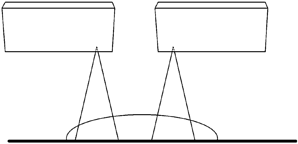
[0052] figure 1 It is a schematic diagram of the sensor position calibration principle provided by Embodiment 1 of the present invention.

[0053] The sensors are arranged and installed according to the parameter characteristics of the measured object and the sensor itself. When arranging and installing, only the characteristics and structure of the measured object and the sensor itself need to be considered. When calibration is required, such as figure 1 As shown, at least one spherical standard with known radius is used, placed at the position of the object to be measured, and multiple (two in the figure) three-dimensional sensors are placed on the spherical standard to scan it to obtain spherical data , the relative positional relationship between these sensors can be obtained by calculating according to the obtained data, and this process is to calibrate the relative positions of multiple three-dimensional sensors. Using the results obtained from the calibration, the dat...

Embodiment 2

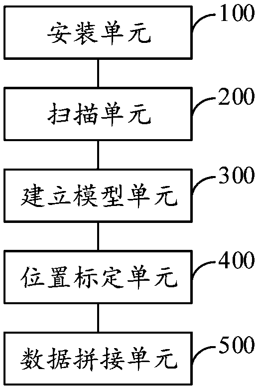
[0087] image 3 It is a schematic diagram of the sensor position calibration and data splicing system provided by Embodiment 2 of the present invention.

[0088] The embodiment of the present invention also provides a system for sensor position calibration and data splicing, which is used to realize the method for sensor position calibration and data splicing in the above-mentioned embodiments. refer to image 3 , the sensor position calibration and data splicing system includes the following units:

[0089] The installation unit 100 is used to set the spherical surface standard and a plurality of sensors at the initial position according to the parameter characteristics of the measured object and the sensor;

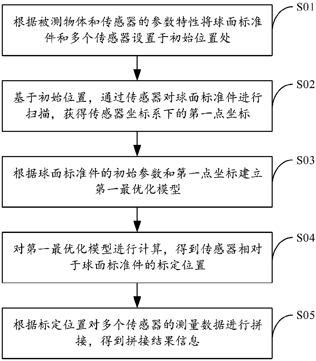
[0090]The scanning unit 200 is used to scan the spherical standard through the sensor based on the initial position to obtain the first point coordinate P in the sensor coordinate system si,k ;

[0091] Establishing a model unit 300 for establishing a first optimiza...


PUM


Abstract

The present invention provides a sensor position calibration and data registration method and system, and relates to the technical field of sensors. The method comprises the steps of: arranging a spherical standard component and a plurality of sensors at initial positions according to a measured object and parameter features of the sensors; based on the initial positions, performing scanning of the spherical standard component through the sensors to obtain first point coordinates under a sensor coordinate system; according to initial parameters of the spherical standard component and the firstpoint coordinates, establishing a first optimizing model; performing calculation of the first optimizing model, and obtaining calibration positions of the sensors relative to the spherical standard component; and performing registration of the measurement data of the plurality of sensors according to the calibration positions to obtain registration result information. The sensor position calibration and data registration method and system can improve the accuracy of calibration and data registration and meet different models of sensors with different precisions for calibration and data registration.

Description

technical field [0001] The invention relates to the technical field of sensors, in particular to a method and system for sensor position calibration and data splicing. Background technique [0002] In actual use, sometimes in order to expand the measurement range of the 3D sensor, multiple 3D sensors need to be used. For example, for a laser 3D sensor with a higher resolution, its measurement range is often relatively small. One approach is to use multiple laser 3D sensors for scanning. In order to scan and obtain the inner groove width of the measured object, two 3D laser sensors need to be placed on both sides of the measured object to scan it, and the relative position of the two 3D laser sensors needs to be known to realize the measurement function. Among the methods actually used at present, there is another method that uses some specific structural parts such as grooves to perform rough calibration and data splicing of two 3D sensors. [0003] The results obtained by...

Claims


Application Information

Patent Timeline
Patent Type & Authority Applications(China)
IPC IPC(8): G01B11/02
CPCG01B11/02
Inventor 周蕊
Owner BOJIE ELECTROMECHANICAL SHANGHAI
Why Eureka
Try Eureka