Solution dedusting device

A dust removal device and solution technology, applied in cleaning methods and utensils, electrostatic cleaning, chemical instruments and methods, etc., can solve problems such as inconvenient operation, troublesome static electricity and dust removal, dust falling back to the surface of objects, etc. Simple, no-tip effect

Active Publication Date: 2018-07-20
成都兴红英汽车销售服务有限公司
View PDF7 Cites 0 Cited by
  • Summary
  • Abstract
  • Description
  • Claims
  • Application Information

AI Technical Summary

Problems solved by technology

[0002] In daily life, a feather duster is usually used to remove dust on the surface of objects. However, when it is dusted, it will cause a large amount of dust to rise up, affecting the indoor air quality, causing the operator to inhale a large amount, and more dust will still fall back to the surface of the object; it can be seen , the cleaning effect of the feather duster is very limited
In view of this, there are currently some electrostatic dust removal products or designs that can be used to absorb dust on the surface of objects. However, this kind of product is usually very troublesome for the removal of static electricity and dust in the later stage, so the operation is more inconvenient

Method used


Image

  • Solution dedusting device
  • Solution dedusting device

Examples


Embodiment 1

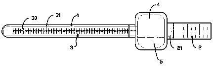
[0014] exist figure 1 In the shown embodiment one, the solution dedusting device includes a hollow rod 1 and a handle 2; the hollow rod 1 is made of an insulator, and a charging shaft 3 is arranged inside it along the axis, and the charging shaft 3 includes a 1 shaft tube 30 extending along the axis, and conical tube groups equidistantly distributed on the shaft tube 30; the tapered tube group includes conical tubes 31 uniformly distributed around the axis of the hollow rod 1 and tapered at the outer end A solution cavity 4 storing a conductive solution 5 is provided between the hollow rod 1 and the handle 2; the conductive solution 5 can only flow in the tapered tube 31, the shaft tube 30, and the solution cavity 4, and The volume of the conductive solution 5 is greater than the total volume of the tapered tube 31 and the shaft tube 30, and smaller than the volume of the solution chamber 4, so that the conductive solution 5 can completely flow into the solution chamber 4, and...

Embodiment 2

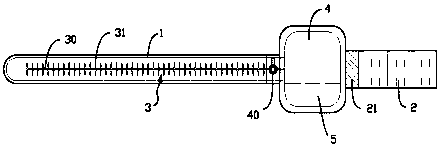
[0018] for figure 2 The second embodiment shown is different from the first embodiment in that a manual valve 40 is also provided between the solution chamber 4 and the shaft tube 30 so that the shaft tube 30 and the solution chamber 4 Stay connected or block. Thus, it can be ensured that the conductive solution 5 is completely kept in the solution chamber 4 when the dust removal device is not in use.


PUM


Abstract

The invention provides a solution dedusting device. The solution dedusting device comprises a hollow rod and a handle; the hollow rod is made of an insulator, a charged shaft is arranged in the hollowrod in the axis direction and comprises a shaft pipe extending along the axis of the hollow rod, and conical pipe sets distributed on the shaft pipe at equal intervals; the conical pipe sets compriseconical pipes which are uniformly distributed along in the circumferential direction of the axis of the hollow rod and provided with pointed-cone-shaped outer ends; a solution cavity storing a conducting solution is formed between the hollow rod and the handle; the conducting solution can flow in only the conical pipes, the shaft pipe and the solution cavity, and the volume of the conducting solution is larger than the total volume of the conical pipes and the shaft pipe and smaller than the volume of the solution cavity; and the handle is internally provided with a high-voltage power module,one output end of the high-voltage power module is electrically connected with a straight wire extending along the axis of the shaft pipe, and the other output electrode of the high-voltage power module is connected to a metal contact zone on the handle after being electrically connected with a current-limiting resistor. After the solution dedusting device sucks dust, the electrostatic effect canbe eliminated easily, dust adhering to the device easily falls, and operation is convenient.

Description

technical field [0001] The invention relates to the field of daily necessities, in particular to a dust removal device. Background technique [0002] In daily life, a feather duster is usually used to remove dust on the surface of objects. However, when it is dusted, it will cause a large amount of dust to rise up, affecting the indoor air quality, causing the operator to inhale a large amount, and more dust will still fall back to the surface of the object; it can be seen , the cleaning effect of the feather duster is very limited. In view of this, there are currently some electrostatic dust removal products or designs that can be used to absorb dust on the surface of objects. However, this kind of product is usually very troublesome for the removal of static electricity and dust in the later stage, so the operation is more inconvenient. Contents of the invention [0003] In view of the above problems, the object of the present invention is to provide a solution dedustin...

Claims


Application Information

Patent Timeline
Patent Type & Authority Applications(China)
IPC IPC(8): B08B6/00
CPCB08B6/00
Inventor 钱月珍
Owner 成都兴红英汽车销售服务有限公司
Why Eureka
Try Eureka