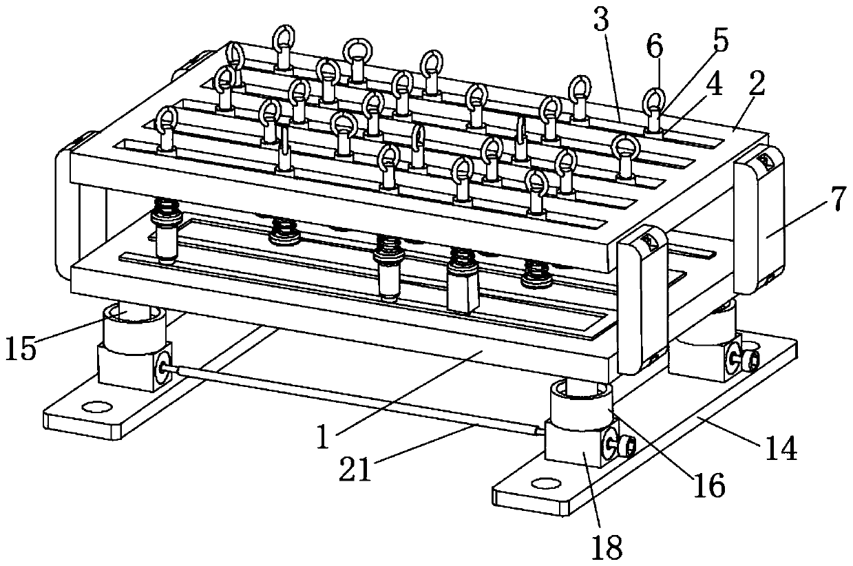
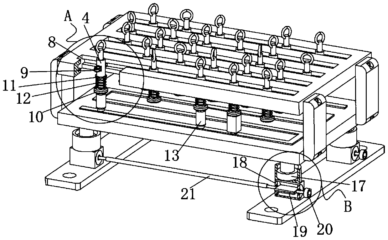
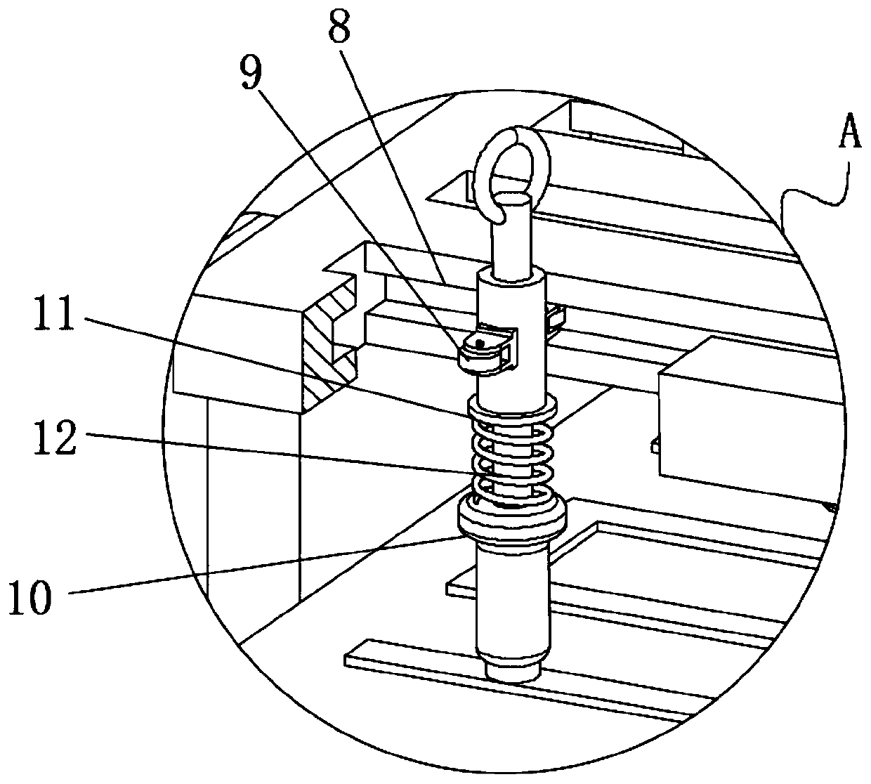
A circuit board fixing device that prevents desoldering and facilitates disassembly and installation

A technology for fixing devices and circuit boards, which is applied in the direction of assembling printed circuits with electrical components and printed circuits connected with non-printed electrical components. It can solve problems such as loose components, desoldering of circuit boards, and inconvenient maintenance. Reduce loss, prevent desoldering, and facilitate disassembly

Active Publication Date: 2020-08-07
SHANGHAI WEILI IND
View PDF9 Cites 0 Cited by
  • Summary
  • Abstract
  • Description
  • Claims
  • Application Information

AI Technical Summary

Problems solved by technology

[0003] However, on the basis of the technical conditions of the existing circuit boards, there are still many deficiencies in the range and convenience of the use of the circuit boards. In the process of using the circuit boards, the phenomenon of circuit board desoldering is easy to occur, and circuit board components It is also easy to fall off during wiring. During use, the components will also loosen due to high temperature, and desoldering will occur. The connecting wires cannot be fixed, which is very scattered, prone to failure, and inconvenient for maintenance.

Method used


Image

  • A circuit board fixing device that prevents desoldering and facilitates disassembly and installation
  • A circuit board fixing device that prevents desoldering and facilitates disassembly and installation
  • A circuit board fixing device that prevents desoldering and facilitates disassembly and installation

Examples


Embodiment Construction

[0025] The specific embodiments of the present invention will be described in detail below in conjunction with the accompanying drawings, but it should be understood that the protection scope of the present invention is not limited by the specific embodiments.

[0026] The following will clearly and completely describe the technical solutions in the embodiments of the present invention with reference to the accompanying drawings in the embodiments of the present invention. Obviously, the described embodiments are only some of the embodiments of the present invention, not all of them. Based on the embodiments of the present invention, all other embodiments obtained by persons of ordinary skill in the art without creative efforts fall within the protection scope of the present invention.

[0027] Before describing the embodiments, some necessary terms need to be explained. For example:

[0028] If terms such as "first"-"second" appear to be used in the present application to de...


PUM


Abstract

The invention discloses a circuit board for preventing desoldering and being convenient to dismount and mount. The circuit board comprises a circuit board substrate, an upper layer frame plate and a mounting substrate, the upper layer frame plate is arranged directly above the circuit board substrate, a plurality of ceramic connecting blocks are fixedly connected between the circuit board substrate and the upper layer frame plate, a plurality of equidistantly arranged horizontal grooves are formed in an upper surface of the upper layer frame plate, a plurality of hollow sleeve columns are arranged in a single horizontal groove, a vertical rod is inserted in each hollow sleeve column, a pull ring is fixedly connected to an upper end of the vertical rod, a chute is formed in a side edge of arectangular strip formed between the two horizontal grooves, and pulleys are fixedly welded on the two sides of the surface of each hollow sleeve column. According to the circuit board disclosed by the invention, a certain hollow sleeve column is moved to a position where an element needs to be welded, the pull ring is hooked by a hook-shaped auxiliary tool to lift the hollow sleeve column, the pull ring is loosened after an electronic element is welded, and a rubber pressing head moves downward under the action of a compression spring to firmly fit with the upper surface of the electronic element, so as to prevent the desoldering of the electronic element.

Description

technical field [0001] The invention relates to the technical field of circuit boards, in particular to a circuit board fixing device that prevents desoldering and facilitates disassembly and installation. Background technique [0002] The circuit board is mainly composed of pads, vias, mounting holes, wires, components, connectors, filling, electrical boundaries, etc. The circuit board system is classified into the following three types, the parts are concentrated on one side, and the wires are concentrated on the other side , because wire only appears on one side, so we just claim that this PCB is called single-sided board. Because the single-sided board has many strict restrictions on the design circuit, only the early circuits use this type of board. The wiring on both sides is called a double-sided board, but to use the wires on both sides, there must be an appropriate circuit connection between the two sides. This kind of circuit is called a guide hole. The guide hole...

Claims


Application Information

Patent Timeline
Patent Type & Authority Patents(China)
IPC IPC(8): H05K1/18H05K3/34
Inventor 王锦秀孙伟钟云彬余涛
Owner SHANGHAI WEILI IND
Why Eureka
Try Eureka