Laser spot welding clamp

A laser spot welding and fixture technology, applied in the field of mechanical tooling, can solve problems such as desoldering and deviation, low product yield, and false welding of products, so as to ensure welding quality, ensure stability, and avoid false welding.

Active Publication Date: 2017-05-31
DONGGUAN CHANGYING PRECISION TECH CO LTD +1
View PDF12 Cites 3 Cited by
  • Summary
  • Abstract
  • Description
  • Claims
  • Application Information

AI Technical Summary

Problems solved by technology

[0002] During the assembly and production process of the workpiece, many auxiliary materials will be fixed on the workpiece through laser spot welding. Generally, the workpiece (such as a mobile phone case) is clamped by the fixture and then welded. However, for the traditional fixture, the workpiece is in the Shaking will occur during spot welding, which will easily lead to false welding, desoldering and misalignment of the product, resulting in low product yield

Method used


Image

  • Laser spot welding clamp
  • Laser spot welding clamp
  • Laser spot welding clamp

Examples


Embodiment Construction

[0026] In order to facilitate the understanding of the present invention, the present invention will be described more fully below with reference to the associated drawings. Preferred embodiments of the invention are shown in the accompanying drawings. However, the present invention can be embodied in many different forms and is not limited to the embodiments described herein. On the contrary, the purpose of providing these embodiments is to make the disclosure of the present invention more thorough and comprehensive.

[0027] It should be noted that when an element is referred to as being “fixed” to another element, it can be directly on the other element or there can also be an intervening element. When an element is referred to as being "connected to" another element, it can be directly connected to the other element or intervening elements may also be present. The terms "inner", "outer", "left", "right" and similar expressions are used herein for the purpose of descripti...


PUM


Abstract

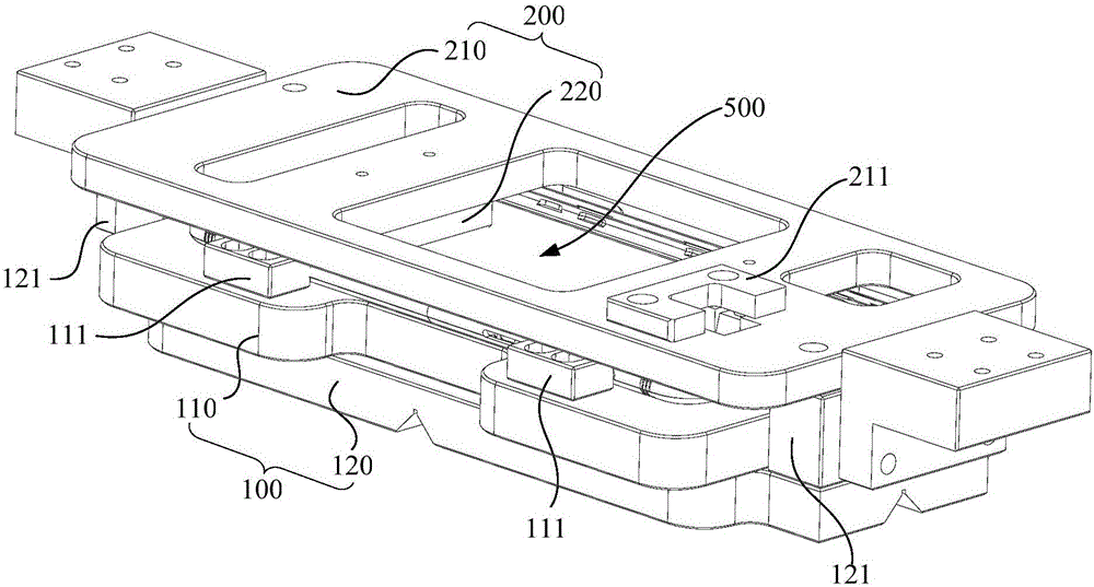
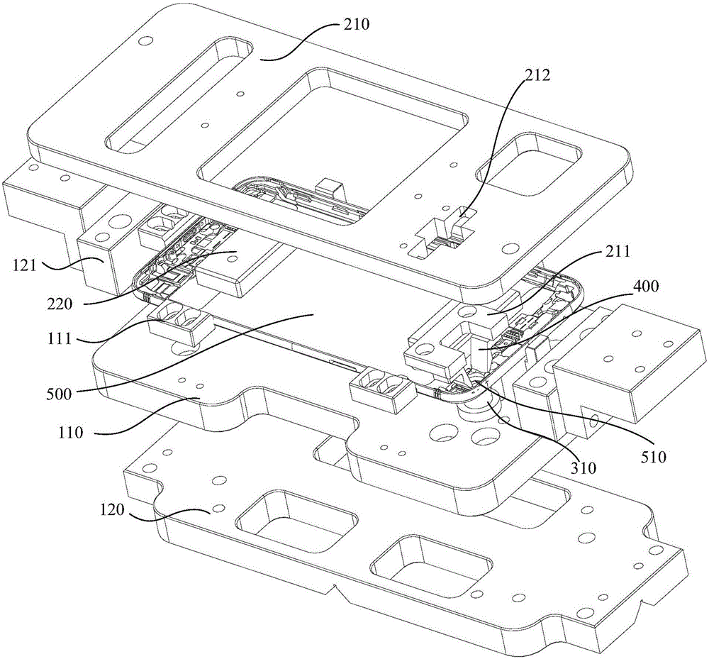
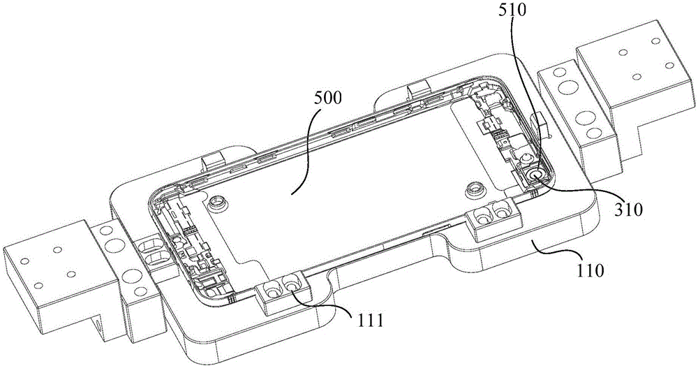
The invention relates to a laser spot welding clamp. The laser spot welding clamp comprises a first clamping mechanism, a second clamping mechanism and a Y-axis positioning mechanism, wherein the first clamping mechanism is provided with X-axis positioning blocks for positioning a workpiece, the second clamping mechanism comprises a second clamping plate connected to the first clamping mechanism and an abutting-pressing part connected to the second clamping plate and used for abutting against the workpiece, and the Y-axis positioning mechanism comprises a positioning column which is arranged on the first clamping mechanism and penetrates through a round hole and an elastic part arranged between the positioning column and the first clamping mechanism. According to the laser spot welding clamp, because only one positioning column is required to be arranged in the round hole of the workpiece in a penetrating mode to realize the positioning of the workpiece in the Y-axis direction, the structure of the clamp is simplified, the positioning precision of the workpiece is improved, the phenomena of false welding, unwelding and deviation in the welding process of an auxiliary material are avoided, and the welding quality of the product is guaranteed; and meanwhile, the clamping capability of the whole clamp is guaranteed, the workpiece is not prone to shake in the spot welding process, and the positioning stability of the workpiece is ensured.

Description

technical field [0001] The invention relates to the technical field of mechanical tooling, in particular to a laser spot welding fixture. Background technique [0002] During the assembly and production process of the workpiece, many auxiliary materials will be fixed on the workpiece through laser spot welding. Generally, the workpiece (such as a mobile phone case) is clamped by the fixture and then welded. However, for the traditional fixture, the workpiece is in the Shaking will occur during spot welding, which will easily lead to false soldering, desoldering and misalignment of the product, resulting in low product yield. Contents of the invention [0003] Based on this, it is necessary to provide a laser spot welding fixture that can improve welding quality. [0004] A laser spot welding fixture, which is applied to the auxiliary material welding of workpieces with round holes, including: [0005] The first clamping mechanism is provided with an X-axis positioning bl...

Claims


Application Information

Patent Timeline
Patent Type & Authority Applications(China)
IPC IPC(8): B23K26/70
CPCB23K26/702
Inventor 周敏
Owner DONGGUAN CHANGYING PRECISION TECH CO LTD
Why Eureka
Try Eureka