
Lamp body structure and landscape lighting device

A lamp body and lamp housing technology, which is applied in the field of landscape lighting, can solve the problems of unsoldering of electrical components, narrow inner space of lamp head, inconvenient detection and maintenance, etc., to avoid virtual welding, improve reliability and production efficiency, and meet large The effect of mass production

Active Publication Date: 2016-08-10
JIAWEI RENEWABLE ENERGY CO LTD
View PDF9 Cites 2 Cited by
  • Summary
  • Abstract
  • Description
  • Claims
  • Application Information

AI Technical Summary

Problems solved by technology

[0009] The technical problem to be solved by the present invention is to provide a lamp body structure and a landscape lighting device. and maintenance is extremely inconvenient and other defects

Method used


Image

  • Lamp body structure and landscape lighting device
  • Lamp body structure and landscape lighting device
  • Lamp body structure and landscape lighting device

Examples


Embodiment 1

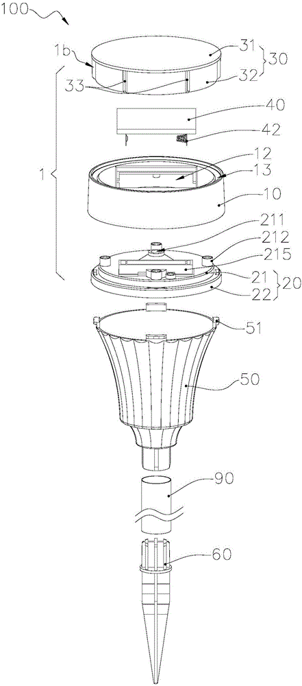
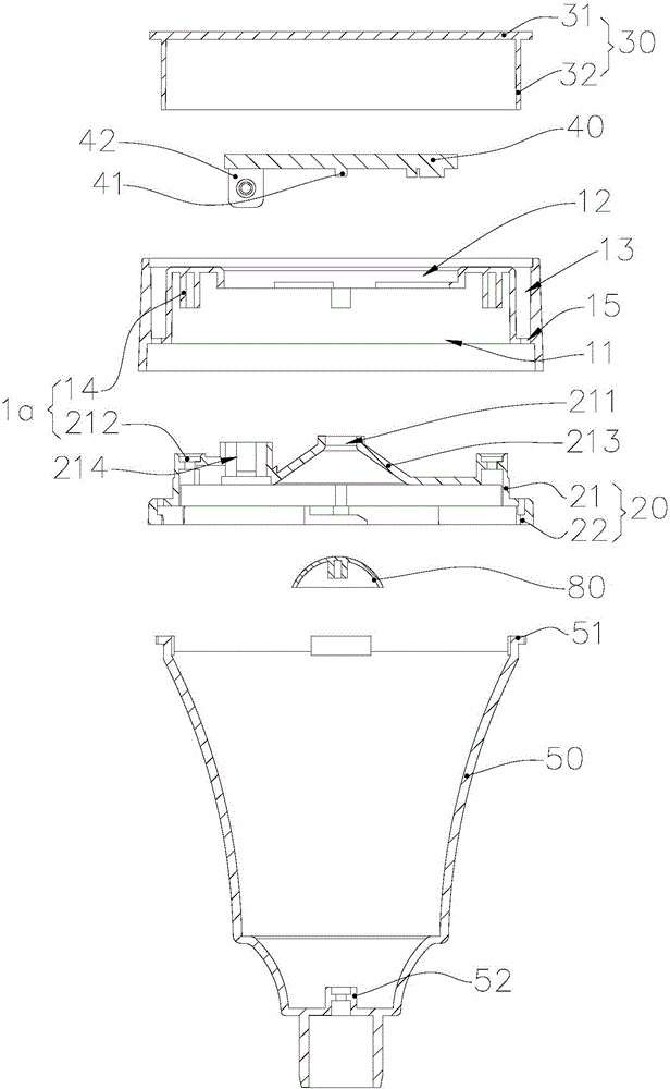
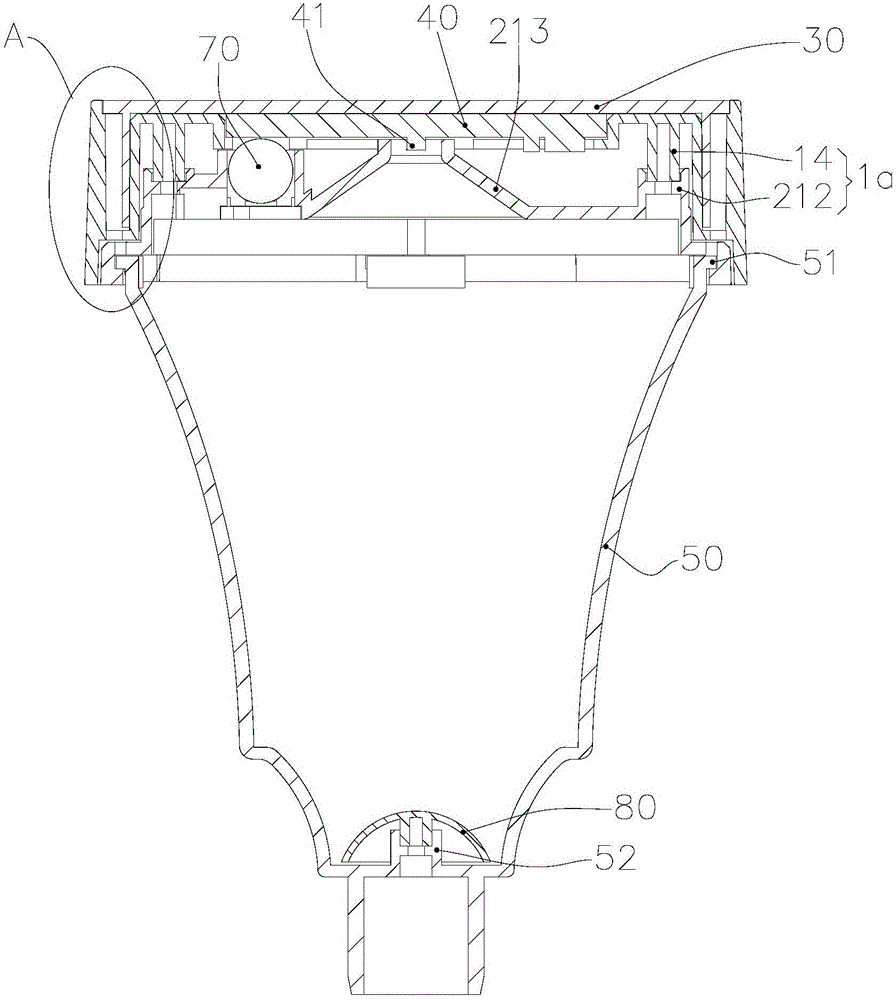
[0064] The landscape lighting device 100 provided in this embodiment includes a lamp body structure 1 composed of a lamp housing 10, a solar cell light-emitting panel 40, a base 20 and a top cover 30, and a lampshade 50 connected to the lamp body structure 1 and supported on Ground cuttings 60 on the lawn.

[0065]The lamp housing 10 is roughly cylindrical and made of plastic or metal integrally formed. The lamp housing 10 is used to install the solar cell luminous panel 40 and support the solar cell luminous panel 40 . Specifically, from figure 1 and 2 It can be seen that a concave cavity 11 with an open lower end is provided in the lamp housing 10 , and a mounting groove 12 is opened in the center of the top surface of the lamp housing 10 . The solar cell light-emitting board 40 is placed in the installation groove 12 , and a protrusion for supporting the solar cell light-emitting board 40 is formed on the inner wall of the installation groove 12 . An accommodating groove...

Embodiment 2

[0088] Attached below Figure 10 and 11 , only the differences from Embodiment 1 will be described in detail.

[0089] In this embodiment, the solar cell 402 is a Sunpower monocrystalline silicon cell. Specifically, the circuit substrate 401 adopts a double-sided panel, and the side surface of the solar cell 402 close to the circuit substrate 401 is provided with a grid line electrode, and the first surface A patterned circuit layer electrically matched with the grid electrode is provided on the top. In this way, the solar cells 402 , the solar cells 402 and the LED lamp bead 41 can be made into one body, thereby eliminating the process of connecting wires among the three, saving production costs and making assembly more convenient.

[0090] Such as Figure 10 and 11 As shown, the fabrication of the solar cell light-emitting panel 40 in this embodiment will be described.

[0091] 1. Fabrication of the circuit substrate 401 , the circuit substrate 401 of this embodiment is...


PUM


Abstract

The invention relates to the technical field of landscape lighting and provides a lamp body structure and a landscape lighting device. The lamp body structure provided by the invention comprises a lampshell, a solar battery lighting slab, a base and a top cover, wherein the lampshell is provided with a cavity for accommodating the base; a mounting groove for arranging and supporting the solar battery lighting slab is formed in the center of the top surface of the lampshell; the mounting groove is communicated with the cavity; the solar battery lighting slab comprises a circuit substrate, an LED (Light-Emitting Diode) lamp bead and a solar battery cell; the circuit substrate comprises a first surface and a second surface which is opposite to the first surface; the LED lamp bead is packaged on the second surface; the solar battery cell is arranged on the first surface; the solar battery cell and the circuit substrate are integrated to form the solar battery lighting slab. Compared with the prior art, the lamp body structure provided by the invention is more convenient to assemble and is convenient to detect and maintain. The landscape lighting device provided by the invention is simplified in structure and capable of satisfying the requirements of large-batch production.

Description

technical field [0001] The technical field of the landscape lighting of the present invention particularly relates to a lamp body structure and a landscape lighting device. Background technique [0002] In most urban lighting projects, solar lawn lights are installed on green lawns, which absorb sunlight during the day and convert it into electrical energy, which can produce very good landscape effects at night. LED lighting is energy-saving and environmentally friendly, and is often used in urban lighting projects. [0003] At present, the solar lawn lamp mainly includes the lamp holder and the solar panel installed in the lamp holder, the circuit control board, the rechargeable battery, and the LED. The assembly is completed through processing techniques such as gluing, electric soldering iron welding connection, and screw fixing to assemble the lawn. Finished lights. [0004] Traditional solar lawn lights have the following shortcomings: [0005] 1. The solar panel and...

Claims


Application Information

Patent Timeline
IPC IPC(8): F21S9/03F21V17/10F21V17/12F21V17/16F21V19/00F21Y115/10F21W131/109
CPCY02B20/72F21S9/037F21V17/10F21V17/12F21V17/16F21V19/001F21W2131/109
Inventor 邹仉才王春苞刘琦刘俊显
Owner JIAWEI RENEWABLE ENERGY CO LTD
Learn More