Conveying device with weighing sensors
A technology of weighing sensors and transmission devices, which is applied in the direction of conveyor control devices, conveyor objects, transportation and packaging, etc., can solve the problems of low efficiency and labor-intensive weighing methods, so as to improve weighing efficiency and reduce worker labor. Strength, Ease of Use and Effects
Inactive Publication Date: 2018-07-20
安徽智敏电气技术有限公司
View PDF5 Cites 0 Cited by
- Summary
- Abstract
- Description
- Claims
- Application Information
AI Technical Summary
Problems solved by technology
[0003] In view of the above-mentioned shortcomings of the prior art, the object of the present invention is to provide a conveying device with a load cell, which is used to solve the problems of low efficiency and a large amount of labor in the existing product weighing method
Method used
View moreImage
Smart ImageViewing Examples

Examples
specific Embodiment approach
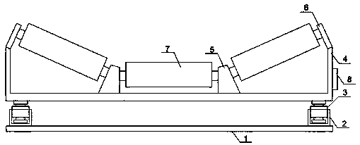
[0017] Specific embodiments: during use, the weighing sensor 3 weighs the product moving on the roller 7, which can eliminate the cumbersome steps of manual weighing and improve the production efficiency of the enterprise.
Login to View More PUM
 Abstract
The invention discloses a conveying device with weighing sensors. The conveying device comprises a bottom plate, limiting groove columns, the weighing sensors, a bottom frame, supporting columns, supporting plates, rollers and a circuit controller. The corresponding limiting groove column is fixedly arranged at each of the four corner positions of the upper plane of the bottom plate through a bolt. The corresponding weighing sensor is fixedly arranged in each limiting groove column through a bolt. The same bottom frame is fixedly arranged on the weighing sensors through bolts. The circuit controller is fixedly arranged on the right plane of the bottom frame through bolts. The two supporting columns are fixedly arranged on the upper plane of the bottom frame through bolts. Each of the upperends of the left side wall and the right side wall of the bottom frame is fixedly provided with the corresponding supporting plate through bolts, and the rollers are rotationally arranged between thetwo supporting columns. The conveying device has the beneficial effects that usage is convenient, the weighing efficiency is improved, and the labor intensity of workers is relieved.
Description
technical field [0001] The invention relates to a conveying device, in particular to a conveying device with a weighing sensor. Background technique [0002] In the process of factory production and processing, different products have different production steps. Some products need to be weighed during the production process. The traditional detection method is for workers to select products and weigh them one by one, but this method is very inefficient. , cannot meet the requirements of large-scale production. Contents of the invention [0003] In view of the above-mentioned shortcomings of the prior art, the object of the present invention is to provide a conveying device with a load cell, which is used to solve the problems of low efficiency and a large amount of labor in the existing product weighing method. [0004] In order to achieve the above purpose and other related purposes, the present invention discloses a transmission device with a load cell, including: a bot...
Claims
Login to View More Application Information
Patent Timeline
 IPC IPC(8): B65G43/08
CPCB65G43/08
Inventor 蔡芝为
Owner 安徽智敏电气技术有限公司
Features
- Generate Ideas
- Intellectual Property
- Life Sciences
- Materials
- Tech Scout
- Unparalleled Data Quality
- Higher Quality Content
- 60% Fewer Hallucinations
Learn More Browse by: Latest US Patents, China's latest patents, Technical Efficacy Thesaurus, Application Domain, Technology Topic, Popular Technical Reports.
© 2025 PatSnap. All rights reserved.Legal|Privacy policy|Modern Slavery Act Transparency Statement|Sitemap|About US| Contact US: help@patsnap.com