Eureka AIR delivers breakthrough ideas for toughest innovation challenges, trusted by R&D personnel around the world.

Traction chain of slag conveyor

A slag scraper and chain technology, which is applied in the direction of drag chains, hanging chains, chain links, etc., can solve the problems of chain wear, spillage, bucket tilting, etc., and achieve the effect of prolonging the service life and preventing materials from spilling

Inactive Publication Date: 2018-07-20
TONGLING QIUJING MACHINERY
View PDF5 Cites 0 Cited by
  • Summary
  • Abstract
  • Description
  • Claims
  • Application Information

AI Technical Summary

Problems solved by technology

[0002] The slagging machine is used to separate solid matter of a certain size from the mixture of liquid and solid. It is a continuous and efficient mechanical slag removal equipment. It is often used in the field of slag removal. , the bucket is fixed by two ring chains and then transported, but during the transmission process, because the ring chains are not fixed, the local movement of the two ring chains cannot be completely synchronized during transmission, causing the bucket to tilt, and then The material in the bucket is spilled, and the friction between the ring chain and the transmission device is relatively large, which will cause wear and tear on the chain after long-term use

Method used


Image

  • Traction chain of slag conveyor
  • Traction chain of slag conveyor
  • Traction chain of slag conveyor

Examples


Embodiment Construction

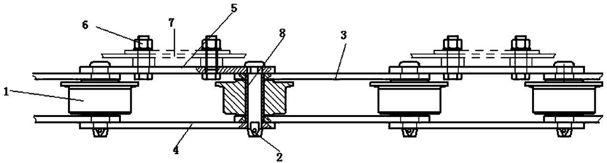
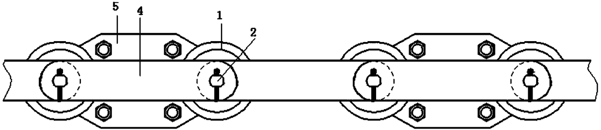
[0018] A slag fishing machine traction chain, such as figure 1 and figure 2 As shown in the figure, it includes a number of chain links that are connected and fixed in sequence. Each chain link includes two rollers 1. A fixing through hole is opened at the center of the surface of the two rollers 1, and a pin shaft 2 is installed in the fixing through hole. Two inner link plates 3 are sleeved and fixed between the pins 2 of the roller 1, the two rollers 1 are connected by the two inner link plates 3, and the two inner link plates 3 are located at the upper and lower ends of the roller 1 respectively. At the same time, one end face of the two inner link plates 3 is pressed and connected with the upper and lower end faces of the roller 1 respectively;

[0019] The two adjacent chain links are connected by the first outer link plate 4 and the second outer link plate 5, and the first outer link plate 4 and the second outer link plate 5 are respectively sleeved and fixed on the t...


PUM


Abstract

The invention discloses a traction chain of a slag conveyor. The traction chain comprises a plurality of chain links which are sequentially connected and fixed, and each chain link comprises two rollers; fixed through holes are formed in the surface centers of the two rollers; hinge pins are mounted in the fixed through holes; two inner chain plates are arranged and fixed between the hinge pins ofthe two rollers in a sleeving manner; the two rollers are connected through the two inner chain plates; the two inner chain plates are separately positioned at the upper and lower ends of the rollers; and one end faces of the two inner chain plates are in press connection with the upper and lower end faces of the rollers separately. The traction chain is composed of the inner chain plates, outerchain plates and the rollers which are mutually connected, friction force between the chain and a transmission roller can be reduced through the guiding function of the rollers during the transmissionprocess, and the service life of the chain is prolonged; and two rollers are arranged in the slag conveyer, a bucket is fixed between the two chains, synchronous motion is achieved through the locating connection function of the bucket, the bucket maintains balanced and does not incline during the transfer process, and materials in the bucket are prevented from being spilt.

Description

technical field [0001] The invention belongs to the field of slag fishing, and relates to a traction chain of a slag fishing machine. Background technique [0002] The slag removal machine is used to separate solid substances of a certain size from the liquid and solid mixture. It is a continuous and efficient mechanical slag removal equipment. It is often used in the field of slag removal. The existing slag removal machine usually uses a circular chain. , the bucket is fixed by two ring chains and then transferred, but during the transmission process, due to the instability between the ring chains, the local movements of the two ring chains cannot be completely synchronized during transmission, causing the bucket to tilt, and then The material in the bucket is spilled, and the friction between the ring chain and the transmission device is large, and the chain wears out after long-term use. SUMMARY OF THE INVENTION [0003] The purpose of the present invention is to provi...

Claims


Application Information

Patent Timeline
Patent Type & Authority Applications(China)
IPC IPC(8): F16G13/12F16G15/12
CPCF16G13/12F16G15/12
Inventor 万林应王二虎刘涛
Owner TONGLING QIUJING MACHINERY
Why Eureka
Eureka Blog
Learn More