Eureka AIR delivers breakthrough ideas for toughest innovation challenges, trusted by R&D personnel around the world.

Permeable grate with screened drain holes with opening and closing doors on upper surface of permeable grate body

A technology of weep holes and grates, which is applied to waterway systems, water supply devices, drainage structures, etc., can solve the problems that it can only be used for cars and roads, and the meticulous work is immature

Active Publication Date: 2018-07-24
陈三军
View PDF8 Cites 1 Cited by
  • Summary
  • Abstract
  • Description
  • Claims
  • Application Information

AI Technical Summary

Problems solved by technology

[0002] In recent years, I have been working hard to experiment with the reform and innovation of the rainwater grate. On June 5, 2017, with the obtained certificate, I applied for the patent of "Water Filter Grate with Water Tank with Weep Hole", patent number: 201720637945.3, 201710412337.7, the drainage channel of design A in this patent must reach a width of 7 cm and a depth of 5 cm to meet the environmental requirements, and can only be used for automobile roads. Design B, the blocking door opens upwards, and the grate absorbs plastics that are lighter than water Other substances will be stuck in the drain, the door will not be closed tightly, and heavy objects such as passing bicycles and cars will crush the door. With the deepening of practice, the product shows that it is immature in responding to the overall environment and meticulous work. Apply for the patent again after the practice

Method used


Image

  • Permeable grate with screened drain holes with opening and closing doors on upper surface of permeable grate body
  • Permeable grate with screened drain holes with opening and closing doors on upper surface of permeable grate body
  • Permeable grate with screened drain holes with opening and closing doors on upper surface of permeable grate body

Examples


Embodiment Construction

[0016] The following examples are used to illustrate the present invention, but are not intended to limit the scope of the present invention.

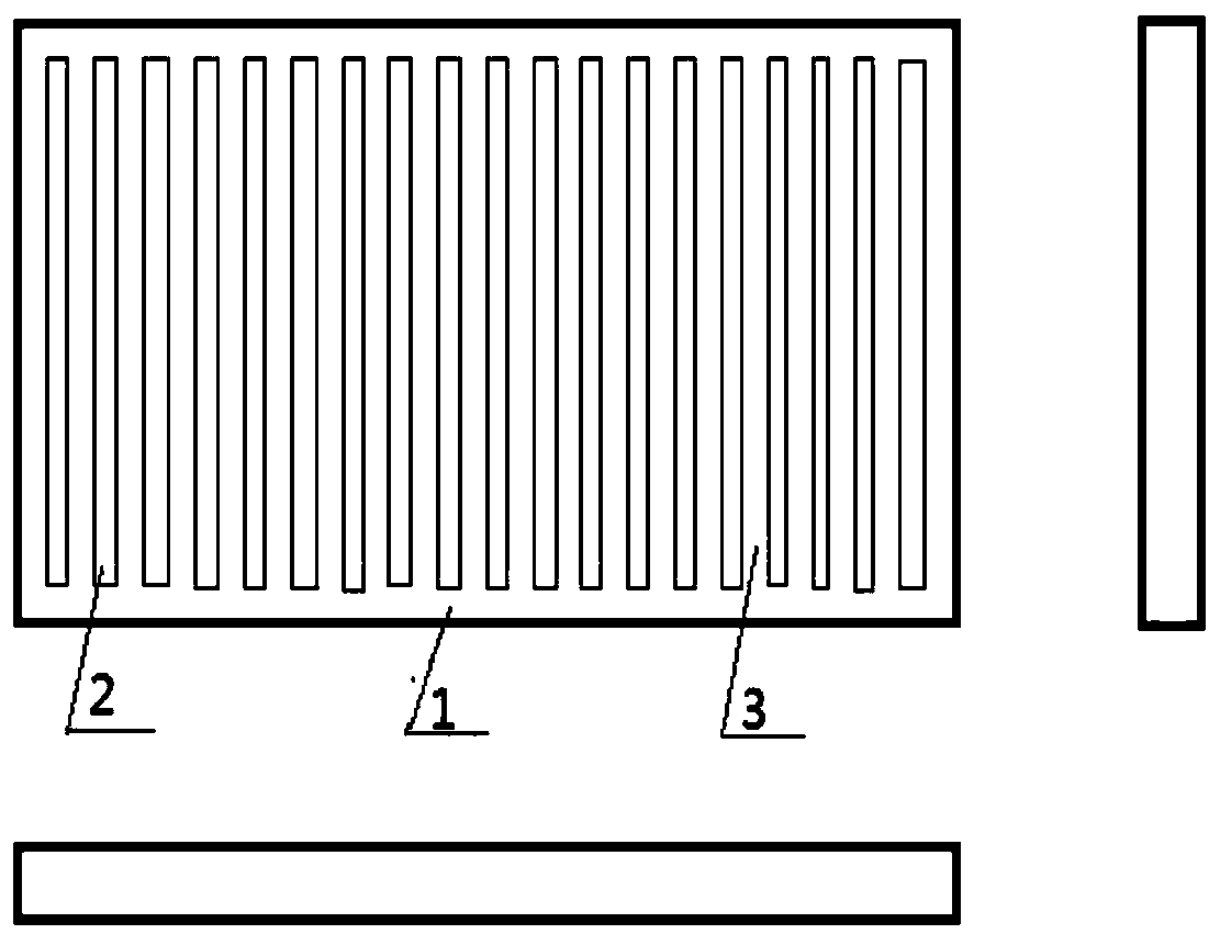
[0017] figure 1 The permeable grate is still in use till now, mainly comprising: a grate frame 1, a water discharge hole 2, and a grate rib 3.

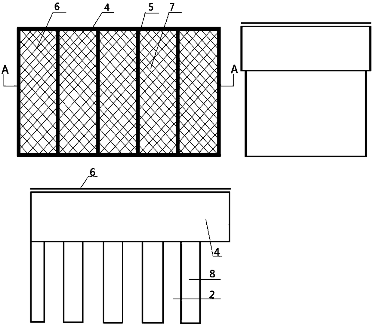
[0018] figure 2 In order to more clearly illustrate the effect of the permeable grate on the upper surface of the permeable grate with mesh drain holes and open and close doors, figure 2 The schematic diagram of the same function shown by each drain hole in the new grate can only be intercepted in an enlarged manner. The main body of the permeable grate with net grate added: grate frame 4, drain hole 2, grate edge 5, net grate 6, barrier Object door 7, water tank 8 form.

[0019] Plan A:

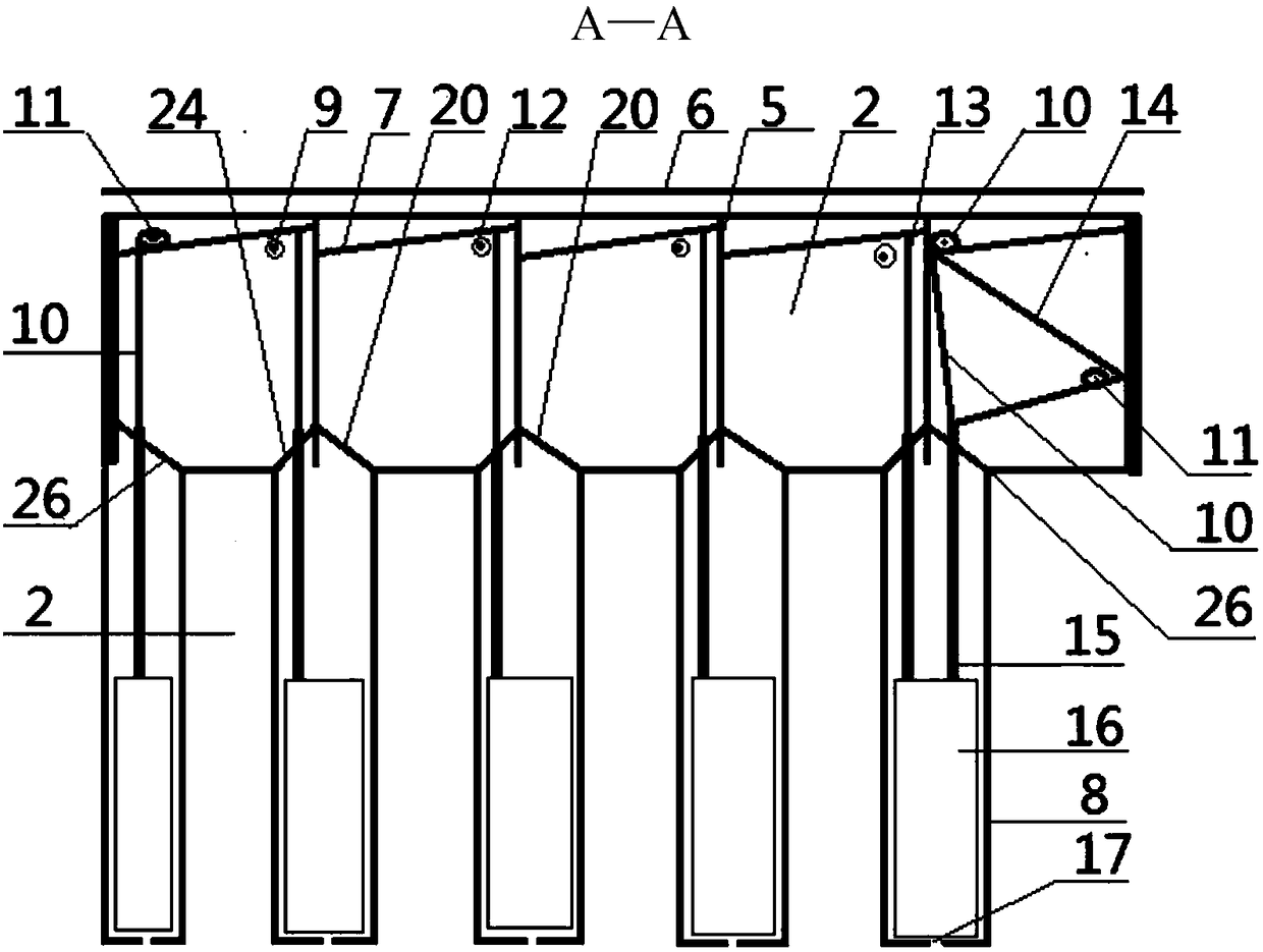
[0020] image 3 1. The permeable grate body upper surface netting drain hole band switch door permeable grate A—A water-free state structure diagram, one end of the pull door rope 10 is connected to t...


PUM


Abstract

The invention relates to a permeable grate with screened drain holes with opening and closing doors on the upper surface of a permeable grate body. 'Nature is managed by nature', a thin, pressure-resistant and non-open-weld screen grate is fixed on the upper surface of the whole grate body by technological means of welding, pull riveting, inlaying, insertion and the like, the doors are arranged atthe edges of the drain holes and opened downwards, two side walls are arranged on the lower portion of each door, a water collecting table is arranged on one side wall, water filtered by the water collecting table is supplied to a water tank with self-cleaning, self-storage and self-draining functions, the water tank is long-lasting in clear water quantity, power energy of the water tank is kept,reciprocating work is performed, an opening and closing door component is arranged on the opposite side wall, a falling door protects an automatic door running component from disturbance of externalenvironments, ropes are balance media for the doors and floating blocks, the permeable grate with the doors is permanently constant and has nature resistance, the use effect of the permeable grate isas same as that of a current permeable grate still in use today, and many subsequent management procedures of drainage projects can be omitted.

Description

technical field [0001] The invention relates to a water suction port facility of a sewage discharge project. Background technique [0002] In recent years, I have been working hard to experiment with the reform and innovation of the rainwater grate. On June 5, 2017, with the obtained certificate, I applied for the patent of "Water Filter Grate with Water Tank with Weep Hole", patent number: 201720637945.3, 201710412337.7, the drainage channel of design A in this patent must reach a width of 7 cm and a depth of 5 cm to meet the environmental requirements, and can only be used for automobile roads. Design B, the blocking door opens upwards, and the grate absorbs plastics that are lighter than water Other substances will be stuck in the drain, the door will not be closed tightly, and heavy objects such as passing bicycles and cars will crush the door. With the deepening of practice, the product shows that it is immature in responding to the overall environment and meticulous wo...

Claims


Application Information

Patent Timeline
IPC IPC(8): E03F5/04E03F5/06
CPCE03F5/04E03F5/0404E03F5/06
Inventor 陈三军
Owner 陈三军
Why Eureka
Eureka Blog
Learn More