Wall replacement support device for reinforced concrete shear wall structure under high load action

A reinforced concrete and support device technology, which is applied to pillars, building structures, and on-site preparation of building components, etc., can solve the problems of narrow construction operation surface, rough structure of support devices, and large load on walls, so as to improve the construction efficiency. Efficiency, simple and clear structure, saving construction cost

Pending Publication Date: 2018-07-24
SHANDONG PROVINCIAL ACAD OF BUILDING RES
View PDF6 Cites 5 Cited by
  • Summary
  • Abstract
  • Description
  • Claims
  • Application Information

AI Technical Summary

Problems solved by technology

The structure of this type of supporting device is relatively simple and rough. There is no accurate load monitoring system during the loading process. The installation and disassembly of the construction device are cumbersome and cannot be operated efficiently. Replacement of lesser components
[0004] However, when the concrete of the high-rise reinforced concrete shear wall is replaced and strengthened, due to the high building height of the shear wall structure, the wall bears a huge load, the force is complicated, and the construction operation surface is narrow.
If the above-mentioned conventional support device is used, the loading is rough, the load on the support device cannot be effectively calculated and monitored, and the loading error is huge. Because the support device is large in size, it is often necessary to destroy the wall reinforcement for crossing the support
Considering the above characteristics, it will lead to an increase in the construction risk factor, construction difficulty and risk.
In addition, the replacement device often has no rated support load, the construction cycle is poor, and the economic benefit is not good

Method used


Image

  • Wall replacement support device for reinforced concrete shear wall structure under high load action
  • Wall replacement support device for reinforced concrete shear wall structure under high load action
  • Wall replacement support device for reinforced concrete shear wall structure under high load action

Examples


Embodiment Construction

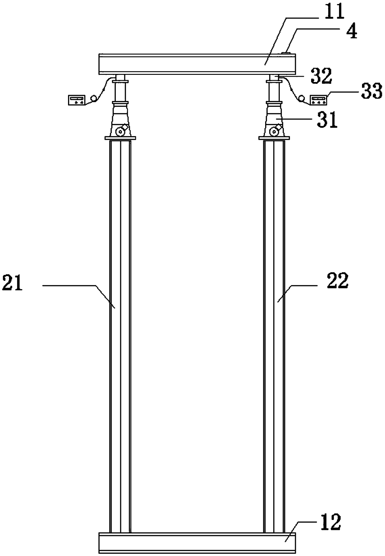
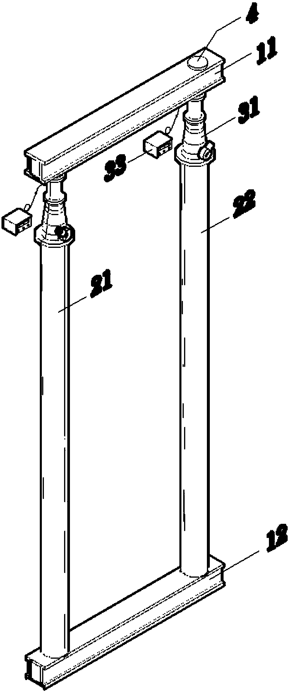
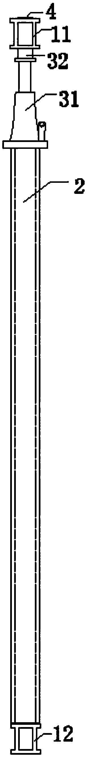
[0017] Refer to the attached figure 1 to attach Figure 5 The wall displacement supporting device of the reinforced concrete shear wall structure of the present invention under high load will be described in detail below.

[0018] The wall replacement supporting device of the reinforced concrete shear wall structure under high load of the present invention comprises a horizontal support system 1, a universal level 4, a vertical support system 2, a load application and monitoring device 3, and the horizontal support System 1 includes an upper beam 11 and a lower beam 12. The upper beam 11 and the lower beam 12 are arranged correspondingly up and down. The upper beam 11 and the lower beam 12 are respectively installed on the wall corresponding to the upper floor of the wall to be replaced and near the wall to be replaced. The position of the wall at the bottom of the floor, the vertical support system 2 includes a left vertical rod 21 and a right vertical rod 22, and the left v...


PUM


Abstract

The invention discloses a wall replacement support device for a reinforced concrete shear wall structure under high load action and belongs to the field of building structure reinforcement. The devicestructurally comprises a horizontal support system, a universal gradienter, a vertical support system and two sets of load applying and monitoring devices, wherein the horizontal support system comprises an upper cross beam and a lower cross beam; the vertical support system comprises a left upright rod and a right upright rod; the left upright rod and the right upright rod are symmetrically arranged between the upper cross beam and the lower cross beam; the two sets of load applying and monitoring devices are respectively arranged at the upper part of the left upright rod and the upper partof the right upright rod; each set of load applying and monitoring device respectively comprises a screw jack, a stress sensor and a stress display, and the stress sensor is electrically connected with the stress display; and the universal gradienter is arranged at the upper part of the upper cross beam. The device disclosed by the invention has the characteristics that the device can be used fortemporarily supporting the wall, then old concrete is chiseled away, and fresh concrete is poured through a formwork, thereby achieving the effect of concrete replacement.

Description

technical field [0001] The invention relates to the field of building structure reinforcement, in particular to a wall replacement support device under the high load of a reinforced concrete shear wall structure. Background technique [0002] At present, in the field of high-rise industrial and civil buildings, concrete structure is still one of the most widely used building structure types. This type has the characteristics of good mechanical performance, fast construction speed, high durability and relatively low construction cost. However, in the process of building construction, due to various reasons such as lax construction control and inadequate technical measures, there are inevitably situations where the structural construction quality does not meet the requirements of the design and related specifications, and its bearing capacity, comfort and stability will be greatly reduced. reduced, thus creating the field of reinforcement of concrete structures. According to...

Claims


Application Information

Patent Timeline
Patent Type & Authority Applications(China)
IPC IPC(8): E04G23/02E04G25/06
CPCE04G23/0222E04G25/06
Inventor 孙建东李海文朱传明李仰贤李军军刘兆瑞崔岩
Owner SHANDONG PROVINCIAL ACAD OF BUILDING RES
Why Eureka
Try Eureka