High-temperature medium pressure pipeline blocking device

A technology for pressure pipelines and plugging devices, which is applied in the direction of pipe components, pipeline systems, pipes/pipe joints/pipe fittings, etc. good question

Inactive Publication Date: 2018-07-24
张桂华
View PDF11 Cites 4 Cited by
  • Summary
  • Abstract
  • Description
  • Claims
  • Application Information

AI Technical Summary

Problems solved by technology

[0002] Pressure pipelines refer to all pipelines that are subject to internal or external pressure. However, for pressure pipelines, not only are they required to withstand high pressure, but also need to work stably for a long time, but due to the harsh working environment, it is inevitable that they will leak. The safest and safest way is to close the pressurized pipeline and then carry out maintenance, but it will seriously affect industrial production or residen

Method used


Image

  • High-temperature medium pressure pipeline blocking device
  • High-temperature medium pressure pipeline blocking device
  • High-temperature medium pressure pipeline blocking device

Examples


Embodiment 1

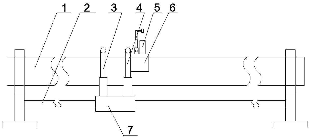
[0064] A high-temperature medium pressure pipeline plugging device, comprising a traveling mechanism 7 arranged on a fixed base at the end of a pressure pipeline 1, an inspection mechanism 3 arranged on the traveling mechanism 7, and an inspection mechanism 3 arranged on the traveling mechanism The blocking mechanism 4 on the 7 and matched with the inspection mechanism 3, and the control mechanism arranged on the running mechanism 7 for controlling the running mechanism 7, the inspection mechanism 3 and the blocking mechanism 4;

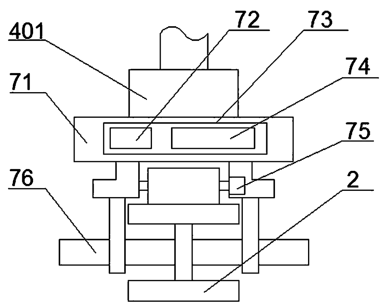
[0065] The traveling mechanism 7 includes a traveling track 2 connected to the fixed base of the pressure pipeline 1, a traveling trolley 71 arranged on the traveling trolley 2, arranged on the lower part of the traveling trolley 71 and opposite to the traveling rail 2. A plurality of driving wheels 76 matched, a driving motor 75 matched with the driving wheels 76 , a cooling mechanism arranged on the walking trolley, and the control mechanism arrange...

Embodiment 2

[0080] The difference from Embodiment 1 is that: a sealing ring matching with the upper end of the sealing tube 5 is provided on the peripheral side of the operation boss 414 .

[0081] It is arranged on the blocking support plate 409 and a multi-layer sealing ring 417 is arranged around the blocking hole 423 .

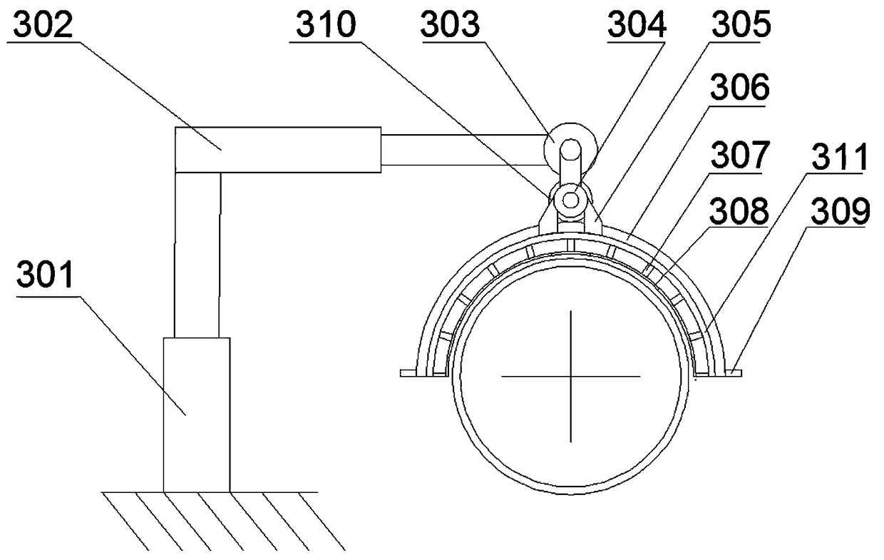
[0082] The radius value of the circle where the arc-shaped blocking guide rail 306 and the arc-shaped inspection guide rail 408 are located is greater than the radius value of the circle on the outer wall of the cross-section of the pressure pipe 1 .

[0083] The arc formed by the arc-shaped blocking guide rail 306 and the arc-shaped inspection guide rail 408 is a semi-circular arc.

[0084] The threaded surface of the sealing plug 4223 is provided with a graphite sealing coating.

Embodiment 3

[0086] The difference from the first embodiment is that the first driving wheel 310 is a helical gear.

[0087] The threaded surface of the sealing plug 4223 is provided with a layer of sealing tape wrapped around it.


PUM


Abstract

The invention provides a high-temperature medium pressure pipeline blocking device which comprises a traveling mechanism, an inspecting mechanism, a blocking mechanism, a cooling mechanism and a control mechanism, wherein the traveling mechanism is arranged on an end part fixing base of a pressure pipeline; the inspecting mechanism is arranged on the traveling mechanism; the blocking mechanism isarranged on the traveling mechanism and matched with the inspecting mechanism; the cooling mechanism is arranged on the traveling mechanism; and the control mechanism is arranged on the traveling mechanism, and used for controlling the traveling mechanism, the inspecting mechanism, the cooling mechanism and the blocking mechanism. By adoption of the high-temperature medium pressure pipeline blocking device provided by the invention, not only can the online blocking operation be achieved, but also the circumstance that when a tool is utilized for treatment, slag from the side wall of a leakinghole falls and pollutes a medium in the pipeline can be avoided; meanwhile, the pipeline can be permanently or semi-permanently repaired, so that the repairing operation on the pipeline during an overhaul can be avoided and just the automatic inspecting operation is needed; and when leaking at high temperature, the pipeline can be temporarily cooled, so that the dangerous environment caused by toohigh temperature can be avoided.

Description

technical field [0001] The invention relates to the technical field of pipeline leakage sealing equipment, in particular to a high-temperature medium pressure pipeline sealing device. Background technique [0002] Pressure pipelines refer to all pipelines that are subject to internal or external pressure. However, for pressure pipelines, not only are they required to withstand high pressure, but also need to work stably for a long time, but due to the harsh working environment, it is inevitable that they will leak. The safest and safest way is to close the pressurized pipeline and then carry out maintenance, but it will seriously affect industrial production or residents' lives, so a plugging device that can be repaired online is needed. There are various plugging devices and methods, but they only perform temporary plugging, but do not achieve long-term stable plugging, or the plugging effect is not good, and there are plugging holes in the online cleaning process. Unneces...

Claims


Application Information

Patent Timeline
IPC IPC(8): F16L55/168F17D5/02
CPCF16L55/168F17D5/02
Inventor 张桂华
Owner 张桂华
Why Eureka
Try Eureka