Blocking method for pressure-bearing pipeline

A technology for pressure-bearing pipes and plugging pipes, which is applied to pipe components, piping systems, pipes/pipe joints/fittings, etc., and can solve problems such as pipeline pollution, poor plugging effect, and impact on industrial production or residents' lives

Active Publication Date: 2018-08-03
张金丹
View PDF4 Cites 1 Cited by
  • Summary
  • Abstract
  • Description
  • Claims
  • Application Information

AI Technical Summary

Problems solved by technology

[0002] Pressure pipelines, that is, pressure pipelines, refer to all pipelines that are subject to internal or external pressure. However, for pressure pipelines, not only are they required to withstand high pressure, but they also need to work stably for a long time. However, due to the harsh working environment, their It is inevitable that there will be leakage. The safest and safest way is to close the pressure-bearing pipeline and then carry out maintenance. However, it will seriously affect industrial production or residents' lives. Therefore, a plugging device that can be repaired online is needed. There are various blocking devices and methods in the prior art, but they only perform temporary blocking, but do not achieve long-term stable blocking, or the blocking effect is not good, and due to online During the cleaning process, there will be unnecessary pollution at the plugging hole, which will cause unnecessary pollution to the pipeline, which will inevitably limit the use of tools for the plugging device

Method used


Image

  • Blocking method for pressure-bearing pipeline
  • Blocking method for pressure-bearing pipeline
  • Blocking method for pressure-bearing pipeline

Examples


Embodiment 1

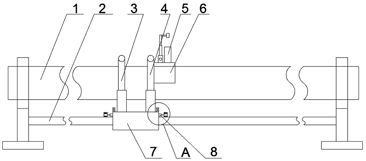
[0064] A pressure-bearing pipeline blocking device, comprising a traveling mechanism 7 arranged on a fixed base at the end of a pressure-bearing pipeline 1, an inspection mechanism 3 arranged on the traveling mechanism 7, and a traveling mechanism 3 arranged on the traveling mechanism The blocking mechanism 4 on the 7 and matched with the inspection mechanism 3, and the control mechanism arranged on the running mechanism 7 for controlling the running mechanism 7, the inspection mechanism 3 and the blocking mechanism 4;

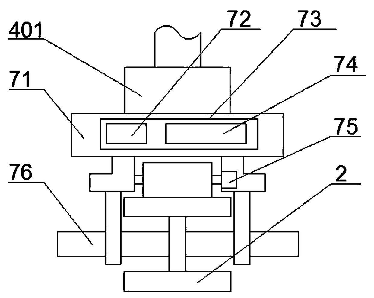
[0065] The traveling mechanism 7 includes a traveling track 2 connected to the fixed base of the pressure pipeline 1, a traveling trolley 71 arranged on the traveling trolley 2, arranged on the lower part of the traveling trolley 71 and the traveling trolley 2 A plurality of driving wheels 76 that cooperate, the driving motor 75 that cooperates with described driving wheel 76, is arranged on described walking dolly 71 and is used for cleaning mechanism 8 that w...

Embodiment 2

[0080] The difference from Embodiment 1 is that: a sealing ring matching with the upper end of the sealing tube 5 is provided on the peripheral side of the operation boss 414 .

[0081] It is arranged on the blocking support plate 409 and a multi-layer sealing ring 417 is arranged around the blocking hole 423 .

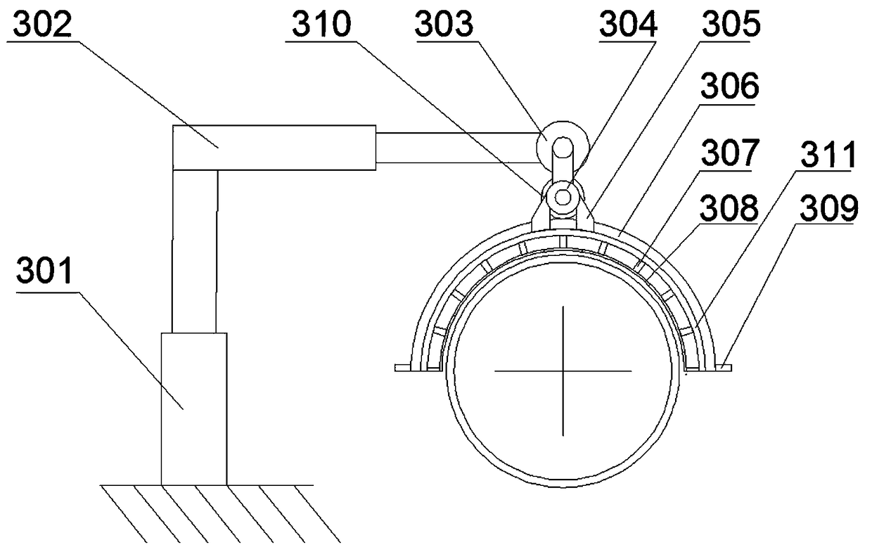
[0082] The radius value of the circle where the arc-shaped blocking guide rail 306 and the arc-shaped inspection guide rail 408 are located is greater than the radius value of the circle on the outer wall of the cross-section of the pressure pipe 1 .

[0083] The arc formed by the arc-shaped blocking guide rail 306 and the arc-shaped inspection guide rail 408 is a semi-circular arc.

[0084] The threaded surface of the sealing plug 4223 is provided with a graphite sealing coating.

Embodiment 3

[0086] The difference from the first embodiment is that the first driving wheel 310 is a helical gear.

[0087] The threaded surface of the sealing plug 4223 is provided with a layer of sealing tape wrapped around it.


PUM


Abstract

The invention provides a blocking method for a pressure-bearing pipeline. Through the steps from S1 to S7, online blocking can be achieved, and during treating by using a tool, the phenomenon that slag of the side wall of a leakage hole falls and thus media in the pipeline are polluted can also be avoided. Meanwhile, the pipeline can be repaired permanently or semi-permanently, the situation thatduring overhauling, the pipeline is repaired again is avoided, and only automatic tour-inspection is needed; and meanwhile, a travelling track can be swept, and thus the phenomenon that due to dust enrichment, the travelling and moving precision is influenced is avoided.

Description

technical field [0001] The invention relates to the technical field of pipeline leakage sealing equipment, in particular to a sealing method for a pressure-bearing pipeline. Background technique [0002] Pressure pipelines, that is, pressure pipelines, refer to all pipelines that are subject to internal or external pressure. However, for pressure pipelines, not only are they required to withstand high pressure, but they also need to work stably for a long time. However, due to the harsh working environment, their It is inevitable that there will be leakage. The safest and safest way is to close the pressure-bearing pipeline and then carry out maintenance. However, it will seriously affect industrial production or residents' lives. Therefore, a plugging device that can be repaired online is needed. There are various blocking devices and methods in the prior art, but they only perform temporary blocking, but do not achieve long-term stable blocking, or the blocking effect is n...

Claims


Application Information

Patent Timeline
Patent Type & Authority Applications(China)
IPC IPC(8): F16L55/162F17D5/02
Inventor 张桂华
Owner 张金丹
Why Eureka
Try Eureka